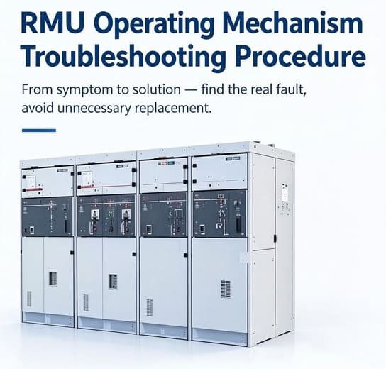

RMU Operating Mechanism Troubleshooting: 10 Common Faults, Causes & Solutions
Introduction
Field‑found failures of Ring Main Unit (RMU) operating mechanisms may introduce unplanned outages and substantial site‑repair costs within medium‑voltage distribution assets. This document is compiled for field service engineers, maintenance technicians and switchgear panel builders, consolidating practical on‑site experience.
It covers mechanism operating principles, diagnostic reference matrix, ten recurrent failure modes, standardized troubleshooting procedures, maintenance check items and key considerations for spare‑part replacement.
Safety Precaution: All troubleshooting activities shall be performed on fully de‑energized, isolated and earthed RMU assemblies. Strictly comply with site‑specific safety regulations.
How Does an RMU Operating Mechanism Work?
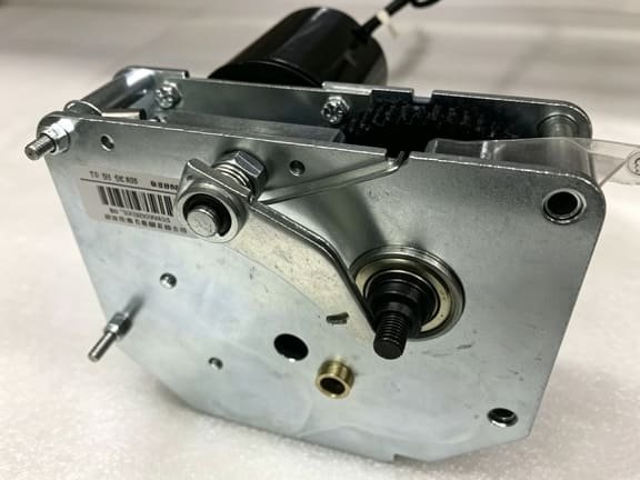
A Ring Main Unit (RMU) operating mechanism converts manual or motor‑driven input torque to complete breaker closing and opening cycles. Typical hardware assembly consists of drive motor, gear transmission unit, spring‑charging module, linkages, mechanical interlocks and auxiliary feedback contacts.
Standard control signal flow:
Control command → Control voltage → Motor / Gearbox → Transmission shaft → Switch mechanism → Auxiliary feedback
Any defect within this signal‑transmission chain will result in abnormal RMU operation. Reliable troubleshooting starts from observed symptoms, followed by differentiation between electrical control anomalies and mechanical component failures.
RMU Operating Mechanism Fault Diagnosis: Quick‑Reference Matrix
Prior to disassembly, apply this matrix to rapidly isolate electrical‑related versus mechanical‑related defects.
| Observed Symptom | First Check Item | Likely Fault Points |
|---|---|---|
| Motor does not run | Control voltage loop | Fuse failure, wiring defect, relay damage, motor winding fault |
| Motor runs but switch cannot actuate | Mechanical transmission path | Coupling slip, gearbox damage, shaft fracture |
| Switch fails to close | Interlock status | Linkage deformation, closing spring fatigue |
| Switch fails to open | Opening circuit & mechanical structure | Control circuit anomaly or mechanical jamming |
| Local operation valid, remote operation invalid | Remote command circuit | Relay malfunction, wiring defect, RTU / SCADA interface fault |
| Position feedback signal mismatch | Auxiliary contact assembly | Limit‑switch damage, linkage misalignment |
| Mechanism operation stiff | Manual mechanical travel | Shaft seizure, gearbox wear, linkage binding |
| Spring cannot complete charging | Charging motor & limit switch | Motor defect, spring‑assembly degradation |
| Mechanism operates sluggishly | Internal mechanical resistance | Lubrication failure, component wear or contamination |
| Intermittent recurrent failures | Overall mechanism condition | Aging wear, component incompatibility |
10 Common RMU Operating Mechanism Faults
1. Stiff or Hard‑to‑Actuate Operating Mechanism
Stiff mechanical travel represents one of the most recurrent field‑encountered mechanical defects. Root causes generally include internal contamination, degraded lubricant, linkage misalignment, gear damage or excessive frictional resistance across transmission assemblies.
Recommended Handling:
- Perform visual inspection to identify mechanical blockage sources.
- Do not apply excessive torque on the operating handle; forced operation may aggravate internal damage.
- Execute component cleaning, re‑lubrication or replacement of worn transmission parts as required.
Diagnostic hint: Where the operating shaft remains constrained even with control power removed, the root cause lies entirely within mechanical assemblies.
2. RMU Switch Cannot Be Closed
Failure to complete closing may stem from mechanical blockage, or non‑delivery of valid closing command signals.
Root‑cause items:
- Engaged mechanical safety interlock
- Non‑compliant operating sequence
- Degraded closing‑spring assembly
- Control‑circuit abnormality
- Linkage misalignment or limit‑switch malfunction
Recommended Handling:
- Verify interlock state as priority step.
- Inspect control‑circuit voltage and wiring continuity.
- Check linkage alignment and spring‑unit integrity.
- Replace defective mechanical components when repair limits are exceeded.
3. RMU Switch Cannot Be Opened
Opening failure can be attributed to control‑circuit defects, solenoid anomalies, motor‑drive faults or mechanical resistance.
Core discrimination logic:
- No electrical command detected → control‑circuit fault
- Valid command received with zero mechanical movement → mechanical‑assembly fault
This differentiation prevents unnecessary full‑mechanism replacement. Inspect transmission and linkage assemblies for jamming or permanent deformation.
4. Motorized RMU Mechanism Fails to Start
Where the drive motor cannot initiate rotation, verify control‑loop voltage prior to judging motor assembly failure.
Inspection sequence:
- Confirm nominal control‑voltage availability.
- Check fuses and protective‑device status.
- Inspect terminal blocks and connector tightness.
- Validate selector‑switch and control‑switch function.
- Measure terminal voltage at motor side while applying operation command.
If rated voltage is present at motor terminals yet no motor response occurs, carry out motor‑assembly replacement.
5. Motor Operates but RMU Switch Remains Stationary
Audible motor‑running output exists, yet no switching action takes place. This indicates intact control‑circuit performance; the defect resides within mechanical transmission segments.
Potential root‑causes:
- Loose motor‑to‑mechanism coupling
- Gearbox internal failure
- Operating‑shaft misalignment
- Linkage structural damage
- Spring‑module failure
Recommended Handling: Inspect coupling, gearbox and full transmission path. Avoid blind motor replacement without mechanical validation.
6. Spring‑Charging Assembly Fails to Complete Charging
Numerous RMU deployments adopt spring‑energy‑storage operating mechanisms. Typical charging‑related anomalies include cyclic motor start‑stop, incomplete spring charging and abnormal operating noise.
Troubleshooting guidance: Inspect charging motor, limit‑switch assembly, field wiring and spring modules. Recurring charging faults indicate progressive mechanical degradation and shall be addressed without delay.
7. Erroneous RMU Position Indication
Position‑feedback deviation originates from mis‑calibrated auxiliary switches, limit‑switch wear, linkage deformation or improper installation settings.
Note: If local manual operation behaves normally while remote monitoring returns incorrect status, focus inspection scope on auxiliary contacts and feedback loops. Adjustment shall strictly follow OEM‑approved technical procedures.
8. Local Operation Valid, Remote Control Inoperative
On‑site manual switching functions normally, while remote commands cannot trigger mechanism action.
Inspection scope:
- Remote command voltage and output‑relay performance
- Selector‑switch setting
- Auxiliary‑position feedback signals
- RTU / SCADA wiring and interface configuration
This fault mode frequently appears on RMUs deployed within distribution‑automation systems.
9. Mechanical Interlock Blocks Mechanism Operation
Mechanical interlocks serve as safety‑critical components to prevent prohibited operating sequences. Interlock bypass is strictly prohibited for temporary commissioning.
Potential causes:
- Non‑standard operating sequence
- Linkage deformation
- Long‑term mechanical wear
- Mis‑positioning of adjacent switching components
Restore mechanism status in accordance with OEM specifications. Repeated interlock tripping indicates latent maintenance requirements.
10. Slow or Erratic Mechanism Operation
Slow, jerky or delayed switching action is caused by lubricant degradation, internal contamination, gear‑linkage wear or overall mechanism aging.
Key inspection points:
- Abnormal noise and vibration signatures
- Switching‑time delay
- Partial‑action recurring phenomena
If cleaning and re‑lubrication cannot restore nominal performance, evaluate full operating‑mechanism replacement.
Standard RMU Operating Mechanism Troubleshooting Workflow
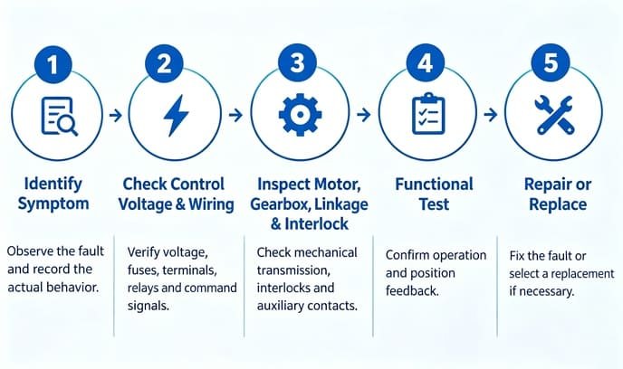
1. Capture accurate symptom information: Record all equipment responses upon operation‑command issuance.
2. Control‑circuit verification: Measure loop voltage, inspect fuses, relays and terminal‑block wiring.
3. Mechanical‑transmission inspection: Examine motor unit, coupling, gearbox, shaft, linkages and spring assemblies for wear, contamination or deformation.
4. Interlock and auxiliary‑contact validation: Confirm safety‑interlock status and feedback‑contact reliability.
5. Functional acceptance test: After fault elimination, perform complete opening‑closing cycle tests under safe working conditions.
RMU Operating Mechanism Maintenance Checklist
Periodic inspection effectively reduces unplanned mechanism‑failure probability.
| Inspection Item | Inspection Content |
|---|---|
| Operating shaft | Smooth travel, no abnormal resistance |
| Linkage & gearbox | No obvious wear, contamination or corrosion |
| Spring assembly | Normal charging and releasing performance |
| Auxiliary contacts | Reliable position‑feedback output |
| Mechanical interlocks | Valid lock‑unlock logic |
| Mounting fasteners | Absence of loose bolts |
Carry out maintenance activities referencing OEM manuals and site‑defined service cycles. Where spare‑part replacement is required, refer to our SafeRing / SafePlus / RM6 operating mechanism for qualified compatible replacement assemblies.
Criteria for Full RMU Operating Mechanism Replacement
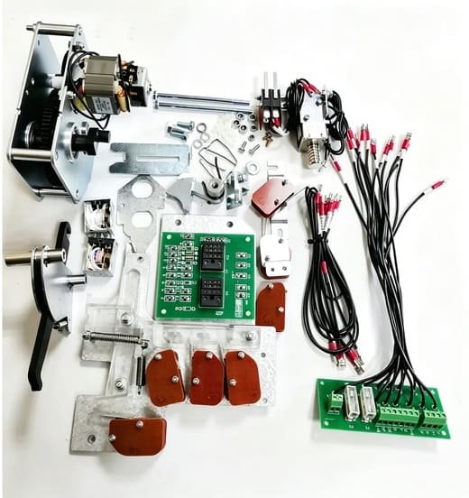
Not all defects require complete mechanism replacement. Minor anomalies such as wiring faults or auxiliary‑contact mis‑adjustment can be rectified on‑site.
Full‑unit replacement is recommended under the following conditions:
- Severe mechanical damage to gearbox or drive shaft
- Spring‑storage assembly fatigue failure
- Multi‑component aging with repeated recurring faults
- Original critical spare‑parts are no longer commercially available
Practical tip: Replacement‑mechanism selection shall be based on RMU model, rated voltage, mounting dimensions, shaft interface and auxiliary‑contact configuration, rather than external appearance only.
If you need drop‑in compatible aftermarket units for RMU cabinet renovation, review our 7S‑R6S‑B‑DC24V operating mechanism for RM6‑S B cabinet, 7S‑SM‑QM motor operator for SM6 QM ring main unit and 7S‑RM‑IM‑E electric operating mechanism for RM6 series cabinets. These aftermarket mechanisms are engineered as compatible alternatives for common European RMU platforms.
Frequently Asked Questions
Q1: Why will my RMU switch not close?
A: Typical contributing factors include active mechanical interlock, non‑compliant operating sequence, control‑circuit failure or degraded closing‑spring assemblies. Differentiate electrical and mechanical root‑causes as the first‑step measure.
Q2: Motor runs, but RMU switch does not move?
A: The control‑circuit remains functional. Inspect motor coupling, gearbox, transmission shaft and linkages for mechanical damage.
Q3: How do you troubleshoot a motorized RMU operating mechanism?
A: Start with control‑voltage measurement and command‑loop verification. Sequentially inspect motor assembly, coupling components, gear units, linkages, interlocks and auxiliary feedback contacts.
Q4: When should an RMU operating mechanism be replaced?
A: Replacement is advised upon severe mechanical damage, spring‑module fatigue, multi‑component aging‑related recurrent faults, or when critical spare‑parts become unavailable.
Q5: Can an RMU operating mechanism be repaired?
A: Minor defects including wiring anomalies and slight mis‑adjustment are eligible for on‑site repair. Heavily worn or fractured core mechanical components generally require full‑unit replacement.