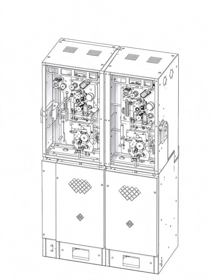

A ring main unit (RMU) is critical to medium-voltage power distribution. Many field incidents happen because crews rush switching or maintenance and skip basic safety checks.
Before you start any work, don’t rely only on the physical switch position. Interlock performance, earthing arrangements, SF6 gas density alarms, control circuits and full isolation procedures all determine whether the job stays safe.
Even small mismatches matter. If remote status readings don’t match local cabinet indicators, stop work immediately. Find the root cause before touching any equipment.
This checklist is for field electrical crews, maintenance engineers and site supervisors. It covers common failure patterns and explains how to spot worn or faulty RMU components that may need replacement.
Safety Notice
This is practical technical guidance only. It is NOT an official switching sequence or work permit document. Always follow OEM manuals, local electrical codes and site safety procedures. The guidance aligns with IEC 62271 series standards for medium-voltage switchgear. Only trained, qualified personnel may operate or service MV switchgear.
Why Use an RMU Safety Checklist?
RMUs combine load-break switches, circuit breakers, earthing switches, mechanical interlocks, operating mechanisms and monitoring sensors. Designs vary widely between manufacturers and product lines.
Common site hazards include misidentified circuits, unexpected energisation, damaged interlocks, abnormal SF6 density readings and incomplete isolation before maintenance starts.
Visual checks can help spot warning signs, but they are not enough on their own. Safe maintenance depends on formal isolation workflows, de-energisation verification, protective earthing and other site safety controls.
Field Note from XiziEnergy service team
We’ve seen multiple close calls where teams trusted cabinet position indicators alone. Where the equipment allows, always cross-check status using two independent indicators. Never rely on a single visual reading.
For EPC Contractors & Switchgear Manufacturers
A well-designed RMU safety system and standard checklist reduce long-term project risk. Proper interlocks, gas monitoring and earthing protection help cut unplanned outages, safety incidents and downtime over decades of operation.
For EPCs and switchgear manufacturers, specifying compliant RMU safety features also helps lower operational risk and procurement liability for distribution projects.
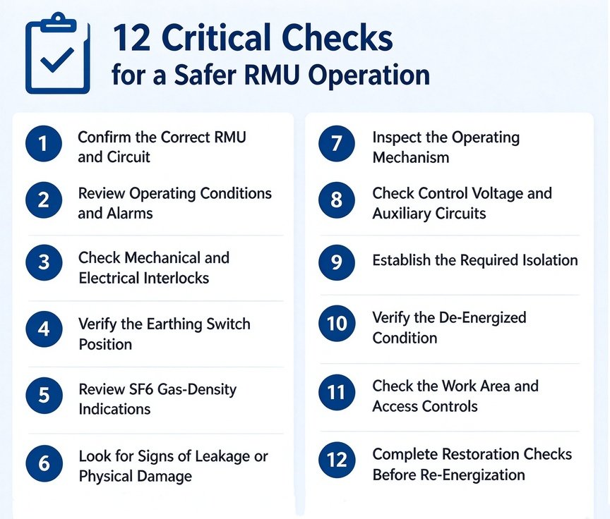
RMU Safety Checklist: 12 Critical Checks
1. Confirm the Correct RMU and Circuit
Check equipment ID tags, feeder names, single-line drawings and approved switching instructions. Make sure the panel you are working on matches the planned scope. Don’t trust labels or memory alone. If there is a conflict between labels, drawings and live status, stop work and resolve it first.
2. Review Operating Conditions and Alarms
Check live status, alarm history and previous operation records. Confirm the work is authorised and compatible with the current network configuration. Unexplained alarms, inconsistent feedback or unusual behaviour needs investigation. A cabinet that looks normal from the outside does not guarantee safe switching.
3. Check Mechanical and Electrical Interlocks
Interlocks are there to stop dangerous operating sequences. Look for physical damage, worn parts or signs that someone forced the mechanism before. Test them only as the OEM manual describes. Never force interlocks or bypass them just to finish the job faster. If something feels wrong, stop and get a controlled technical check.
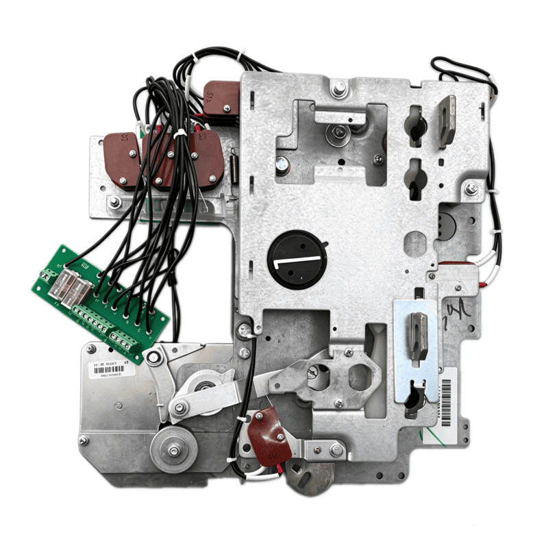
Related guide: RMU Mechanical Work Principle and Troubleshooting
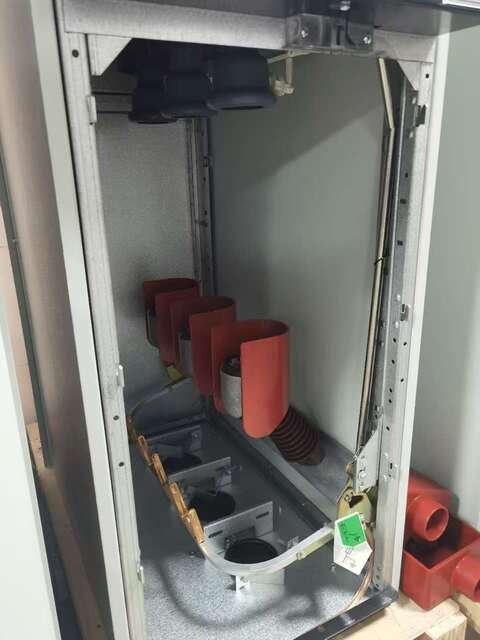
4. Verify the Earthing Switch Position
Use panel indicators and standard procedures to confirm the earthing switch status. Make sure the planned operation matches the RMU layout and interlock logic. Protective earthing must be applied only at the right step in the approved isolation procedure. An open breaker or load-break switch does not guarantee safe earthing by itself.
Related guide: RMU Earthing Switch Guide
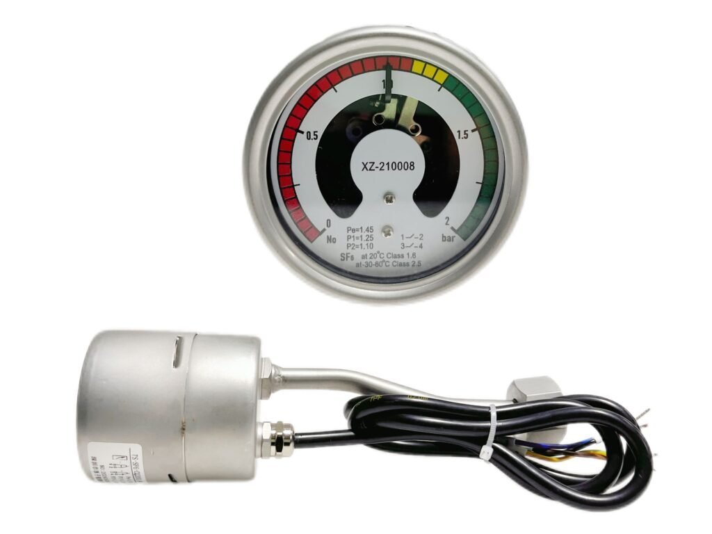
5. Review SF6 Gas-Density Indications
For SF6-insulated RMUs, check the gas-density meter, active alarms and historical logs. Alarms can mean real gas loss, temperature effects, instrument issues or monitoring-circuit faults. Don’t ignore them just because the RMU ran fine yesterday.
Field tip: Outdoor cabins often have wide temperature swings. These can trigger temporary SF6 density alarms. Rule out temperature effects before replacing monitors.
Follow OEM limits and site rules before continuing operation. For non-SF6 RMUs, use the product-specific technical requirements.
6. Look for Signs of Leakage or Physical Damage
Check for cracked enclosures, corrosion, degraded seals and damaged monitoring instruments. Use certified leak detectors when required. Do not open pressurised compartments or do unapproved repairs. Suspected leakage or damage must be handled through formal maintenance and environmental procedures.
7. Inspect the Operating Mechanism
Look for damage or erratic movement in motors, linkages and spring-charging parts. If the RMU does not open or close on command, do not keep pressing the button or force it. Write down the symptoms and equipment state first, then run a controlled diagnosis.
8. Check Control Voltage and Auxiliary Circuits
For motorised RMUs, check control power, local/remote selector position, command channels and auxiliary feedback. Remote failures can come from power loss, relay issues, interlock blocking, wiring faults or bad feedback. Test before you conclude anything. Never short terminals or disable protective logic just to move the switch.
9. Establish the Required Isolation
Before maintenance, identify all energy sources, including back-feed power and auxiliary supplies. Use approved isolation and site lockout/tagout procedures. Buttons, selectors and interlocks are not substitutes for proper electrical isolation. If the boundary or supply source is unclear, do not proceed.
10. Verify the De-Energized Condition
Position indicators, SCADA displays and voltage presence indicators are not proof that a circuit is dead. Qualified technicians must use calibrated test instruments to confirm zero voltage. Follow site procedures, and apply protective earthing where required after verification. Never start work just because a switch looks open.
11. Check the Work Area and Access Controls
Confirm the work scope, permit validity, barriers, signage, PPE and communication plan. Keep access and emergency routes clear. If equipment, scope or grid status changes, reassess the risks before continuing.
12. Complete Restoration Checks Before Re-Energization
Follow the formal return-to-service procedure. Make sure maintenance is done, tools are removed, covers are back on and personnel are clear. Temporary earthing and lockout/tagout devices must be removed through authorisation. Only approved staff can restore supply. Watch for abnormal readings after energisation.
Two Engineering Fault Scenarios
Note: These are educational examples, not actual customer site records. They show how to structure a diagnosis.
Case 1: RMU Does Not Accept a Switching Command
Symptom: The operator sends a command, but nothing happens. Local and remote status may not match.
Possible causes: Control power lost, interlock blocking, relay or wiring fault, incorrect auxiliary feedback.
What to do: Stop sending commands. Check the actual equipment state, alarm logs, selector position and OEM manual. Test control circuits and feedback under authorised procedures.
Lesson: A failed command is not always a bad mechanism. Check the control path, interlocks and feedback first.
Case 2: SF6 Density Alarm Appears During Inspection
Symptom: The density monitor alarms, but the cause is unclear.
Possible causes: Real gas loss, temperature drift, instrument fault, monitoring-circuit fault.
What to do: Record the timestamp, equipment details and readings. Follow OEM and site procedures. Test the monitor, connections and gas condition. Run leak detection if needed.
Lesson: Do not replace the monitor immediately. First decide whether the alarm comes from the gas system or the monitoring side.
Printable RMU Maintenance Safety Checklist
Download this RMU safety checklist as a printable PDF for on-site maintenance records.
This table is for recording only. It is not a substitute for official switching orders, work permits or isolation records.
| Check Item | Record |
|---|---|
| Correct panel and circuit identified | Pass / Action required |
| Operating conditions and alarms reviewed | Pass / Action required |
| Interlocks checked according to procedure | Pass / Action required |
| Earthing-switch position verified | Pass / Action required |
| SF6 density indications reviewed, where applicable | Pass / Action required |
| Visible damage or leakage concerns assessed | Pass / Action required |
| Operating mechanism reviewed | Pass / Action required |
| Control supply and auxiliary circuits checked | Pass / Action required |
| Required isolation and energy controls applied | Verified / Not verified |
| De-energized condition verified by qualified personnel | Verified / Not verified |
| Work-area and permit requirements checked | Pass / Action required |
| Restoration checks completed before re-energisation | Completed / Incomplete |
Any unresolved safety issue must be fixed before work continues.
When Should RMU Components Be Inspected or Replaced?
Look closer when you see repeated mechanism faults, persistent interlock problems or recurring SF6 density alarms. Before ordering parts, confirm the RMU model, part number, ratings, control voltage, mounting size and mechanical/wiring interface. Similar appearance does not mean compatibility.
Always use the actual installed hardware and verified specifications. Replacement components should comply with IEC 62271 for MV switchgear parts.
Frequently Asked Questions
Q: What checks are needed before RMU switching?
A: Confirm the right circuit, authorised instructions, alarms, interlock status and earthing status. Follow the equipment-specific sequence. Stop if something does not match.
Q: Why are RMU interlocks important?
A: They stop you from doing dangerous operations in the wrong order. If an interlock acts abnormal, investigate it. Never bypass it.
Q: Can I work on an RMU when the SF6 density alarm is on?
A: Not until you find the cause. Follow OEM and site rules. Verify the alarm reason and confirm safety before starting maintenance.
Q: How do I find a compatible RMU replacement mechanism?
A: Get the RMU model, nameplate data, part photos and functional requirements. Check control voltage and mounting details. Compatibility depends on the actual configuration, not looks.
Need Help Identifying an RMU Replacement Component?
If you have RMU mechanism faults, interlock issues or SF6 monitoring problems, send us the equipment details and a clear fault description.
XiziEnergy’s team can help assess compatibility for RMU operating mechanisms, auxiliary contacts, earthing-switch assemblies and gas-density monitoring parts.
Submit your RMU model, nameplate parameters, component photos and fault details. Our team will assess part compatibility. All compatibility checks must be done before purchase and installation.
Disclaimer: References to third-party brands are for compatibility context only. They do not mean authorisation, partnership or affiliation. All guidance aligns with IEC 62271 and is for reference only.