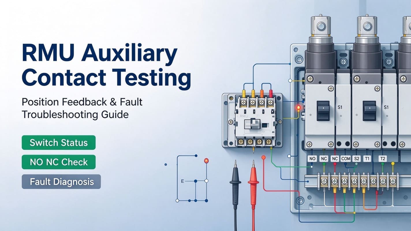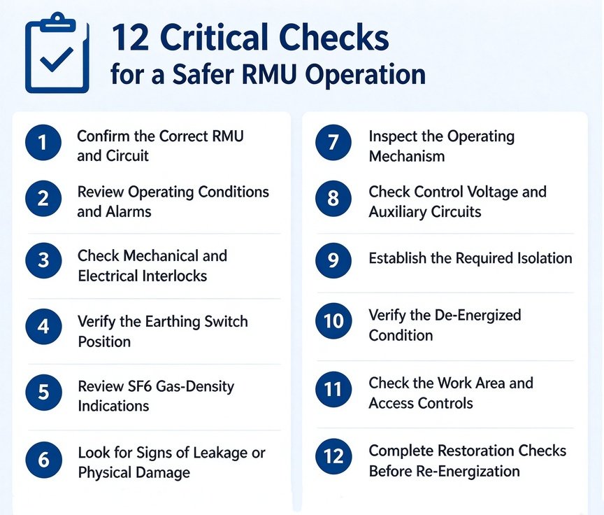

Inside medium-voltage switchgear, RMU mechanical interlocks create a robust physical safety barrier, built entirely from plain metal components. This hardware stops operators from executing risky switching steps out of the correct order, while also synchronising movement between load break switches and earthing switches.
You will run into interlock lockouts regularly when working on these cabinets out in the field. An RMU may simply refuse to close. The earthing switch won’t shift. And the cable compartment door stays firmly locked.
Don’t immediately assume you’re dealing with a broken component — I’ve encountered this scenario countless times. Most often, the interlock is working exactly as intended, preventing an unsafe switching operation. Where genuine faults do show up, they usually stem from worn parts, incorrect operating steps taken by site technicians, or unseen damage hidden within control linkages.
For maintenance crews, asset managers, and buyers sourcing spare hardware, understanding how RMU interlocks behave can cut hours off troubleshooting work. It also helps you select replacement hardware that will properly fit your specific cabinet model.
1. What Is an RMU Mechanical Interlock?
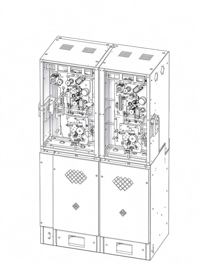
Ring Main Units (RMUs) are compact medium voltage switchgear widely deployed within electrical distribution networks. Cabinet designs can vary significantly from one manufacturer, or even between different models from the same brand. Within each unit, you will find load break switches, earthing switches, cable compartments, operating mechanisms, protection relays, plus a range of control accessories.
This set of physical hardware restricts movement, enforcing a strict sequence for all operations. The assembly includes locking pins, locking plates, operating levers, connecting rods, cams, mechanical stops, drive shafts, and door locks. As one straightforward example: you cannot engage the earthing switch while the main switch remains live and closed.
Bear in mind, interlock designs are not universal. Rules that apply to one cabinet model may not transfer directly to another. One critical point to keep front of mind: mechanical interlocks alone cannot cover every safety requirement when working near energised medium voltage equipment.
Why Interlocking Matters in Medium-Voltage Switchgear
Interlock systems prevent these hazardous operating scenarios:
- Attempting to actuate the earthing switch while the main circuit switch stays closed.
- Closing the main switch when the earthing switch is engaged, where the cabinet design forbids this action.
- Opening cable compartment covers before isolation and earthing procedures have been fully completed.
- Any switching action that violates the OEM’s specified operating sequence.
Remember, interlocking is just one safety layer. It can never replace proper isolation procedures, zero-voltage checks, site earthing protocols or lockout-tagout safety practices.
2. RMU Interlocking System: How Does It Work?
The core principle is fairly simple: the physical position of one component determines which subsequent operations you are allowed to carry out. Take a standard RMU feeder fitted with load break and earthing switches as a real-world field example.
Field technicians first open the load break switch following approved site switching protocols. The circuit must then be fully isolated, and zero voltage verified. Only once all mechanical and safety criteria are satisfied will the interlock unlock the earthing switch for operation. Once the earthing switch locks into its earthed position, a separate door interlock may then release the cable compartment lock. Before restoring power, technicians need to secure the compartment and reset the earthing switch according to the OEM’s operation manual.
This arrangement is common, though not every cabinet functions in exactly this way. Always reference the unit’s interlock diagram and manufacturer documentation before beginning any on-site work.
Typical RMU Interlocking Logic
| Device condition | Possible response |
|---|---|
| Main switch ON | Earthing-switch operation may be blocked |
| Earthing switch earthed | Main switching may be blocked |
| Cable compartment not secured | Closing may be inhibited |
| Electrical permissive missing | Motorized closing may be rejected |
| Trapped key unavailable | Next step in key sequence prevented |
3. Mechanical Interlock vs Electrical Interlock
| Feature | Mechanical | Electrical |
|---|---|---|
| Principle | Physical blocking of movement | Electrical permissive / control logic |
| Components | Levers, shafts, cams, pins, locking plates | Aux contacts, relays, limit switches, wiring |
| Application | Prevent unsafe manual mechanical operations | Block remote or motorised electrical commands |
| Typical fault | Misalignment, wear, bent linkage | Lost control voltage, faulty auxiliary contact, wiring defect |
| Aux power dependence | Still functional without control power | Relies on control circuit supply |
| Troubleshooting focus | Mechanical wear and actual shaft position | Control circuit, permissive signals, position feedback |
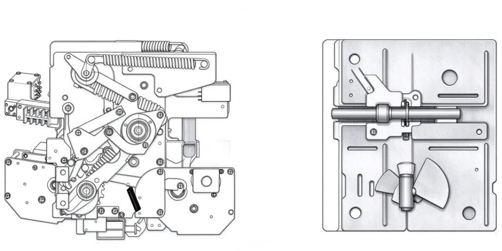
3.1 Mechanical interlock.
A cam or locking plate physically stops shaft rotation until the linked component reaches its permitted position. I’ve seen plenty of on-site failures caused by worn contact surfaces, bent linkages, shaft misalignment, corrosion or snapped locking pins.
3.2 Electrical interlock.
Aux contacts, relays and limit switches grant or deny switching commands. For motorised RMUs, the closing circuit relies on the earthing-switch state, control supply voltage, local/remote selector setting and model-specific permissive rules. A vital field reminder: electrical status signals don’t always reflect the true mechanical position of your switch. Damaged auxiliary contacts can send misleading feedback signals.
3.3 Trapped-key interlock.
This setup manages key release to enforce the required operating sequence. It can control multiple switches and cabinet access doors across an entire switchgear bay. Common faults include damaged lock cylinders, worn keyways and assembly misalignment. Never force keys or swap them to bypass the factory-designed operating sequence.
3.4 Combined mechanical + electrical interlock.
Many motorised RMUs use both systems side-by-side. Mechanical hardware physically blocks motion, while the control circuit rejects remote close commands whenever permissive conditions are not met. While troubleshooting, test these systems separately. Repairing wiring faults won’t confirm that your mechanical interlock operates correctly.
4. Common RMU Interlock Problems and Their Causes
Field case (Turkey 12kV outdoor RMU): One maintenance team reached out to us, reporting that their earthing switch would not close. Upon inspection, we found the interlock cam had worn down after years of outdoor thermal cycling and accumulated dust. The local indicator showed the main switch open, yet the mechanism travel was incomplete. After replacing the cam and linkage assembly, the full interlock sequence returned to normal. Field note: Outdoor RMUs experience far faster cam and pin wear compared with indoor cabinet installations.
When troubleshooting, start by documenting your symptoms. A blocked operation does not automatically mean your interlock has failed. Quite often, the interlock is stopping an unsafe operation from happening.
| Symptom | Possible causes | Direction |
|---|---|---|
| Earthing switch can’t operate | Wrong sequence; main switch not in permitted state; damaged linkage | Verify sequence and real mechanical position |
| RMU switch can’t close | Earthing switch engaged; interlock physical block; missing electrical permissive | Check interlock logic and position indications |
| Mechanical interlock stuck | Wear, corrosion, dirt build-up, misalignment | Inspect only after equipment is safely isolated |
| Cable compartment door won’t open | Isolation/earthing conditions unmet; door interlock damaged | Confirm safe isolation before opening |
| Motorized RMU won’t close remotely | No control voltage; defective aux contact; unsatisfied permissive | Review control schematic and alarm logs |
| Indication mismatches actual mechanism | Aux contact drift, linkage adjustment error, wiring fault | Treat this as safety-critical defect |
| Interlock works intermittently | Wear, loose terminals, unstable contacts, misalignment | Log conditions and isolate the failing subsystem |
This table lists potential causes only, not confirmed root diagnoses. All inspection and repair work must strictly follow OEM documentation.
4.1 Earthing switch interlock problems.
First confirm the main switch state matches your RMU model’s requirements. Other common issues include damaged locking hardware, incomplete operating travel, or mismatch between indicator readings and real mechanical position. Cross-check cabinet model and required sequence, verify all status feedback. Never rely solely on visual indicators to confirm electrical isolation. If the mechanism stays blocked, arrange inspection by certified medium voltage technicians. Do not force the earthing switch or bypass interlocks.
4.2 RMU switch cannot close.
The earthing switch might still remain engaged. Physical interlock hardware could block travel, or required electrical permissive signals may be missing. Motorised cabinets also fail due to lost control supply or faulty auxiliary contacts. Review interlock logic, status indicators, alarms and control schematics.
Work out whether the block originates from mechanical or electrical sources before attempting any repairs. Do not short interlock contacts or energise closing circuits to force switch operation. If your RMU still fails to operate after checking interlock logic, review our full guide about RMU not opening or closing troubleshooting.
4.3 RMU interlock mechanism stuck.
Stiff or jammed hardware can come from wear, corrosion, contamination, misalignment or bent linkages. Remember: mechanical resistance may simply mean the interlock correctly blocks an unsafe operation. Stop all operation attempts right away. Once full lockout and isolation are complete, qualified technicians can inspect accessible locking plates, pins, shafts and levers. Avoid applying heavy force, makeshift tools or non-approved lubricants.
4.4 Motorized RMU remote closing failure.
Even if local operation works fine, remote closing can fail. Root causes range from lost control voltage, incorrect local/remote selector setting, missing permissive conditions, failed relays, wiring damage or inconsistent position feedback. Break your diagnosis down into command transmission, control power, permissive logic, actuator movement and position feedback. Always refer back to factory wiring diagrams.
For motor, transmission and operating mechanism faults, see our guide on RMU operating mechanism troubleshooting.
5. RMU Interlock Troubleshooting Checklist
Use this practical workflow; it can help you avoid replacing a full operating mechanism when only a small interlock component or control circuit is faulty.
Start by writing down your observed symptom. Note the affected device, the operation you tried to perform, displayed position readings, alarms, and whether the fault occurs during local or remote control. Read the manufacturer operating instructions for your exact RMU model and confirm the approved operating sequence. Carefully compare position readings. Any mismatch between displayed status and real mechanical position needs investigation first. Work through electrical permissives. Inspect control supply, auxiliary contacts, relay logic, selector switches and wiring. After isolation and lockout, inspect the mechanical interlock. Check parts for wear, deformation, corrosion, loose fasteners and misalignment. Run manufacturer functional tests after repairs, and confirm the complete interlock sequence works before returning the RMU into service.
Safety note: Never perform live internal inspection or bypass interlocks as a troubleshooting shortcut. All testing and maintenance must be completed by certified medium voltage personnel following local safety regulations.
6. When Should an RMU Interlock Mechanism Be Replaced?
Plan replacement for interlock components once parts crack, permanently deform, wear past OEM limits, or cannot maintain the required switching sequence after approved adjustment and repair work.
Before ordering replacement parts, confirm these details: RMU OEM and model, rated voltage and cabinet configuration, main switch + earthing-switch layout, operating shaft dimensions and mounting interfaces, mechanical travel and locking positions, auxiliary contact configuration, control voltage and electrical interfaces, compatibility test requirements.
A simple physical fit does not guarantee functional compatibility. Replacement hardware must preserve the original interlock logic.
For motorized retrofit projects, see our guide for RMU operating mechanism motorized replacement & retrofit.
What to Submit for Compatibility Check
To match a suitable interlock or operating mechanism, share manufacturer and model, nameplate rated data, clear photos of existing mechanism and mounting structure, part number (if available), observed fault and affected operation, plus control voltage and interface details for motorised RMUs.
7. RMU Interlocking System Maintenance
Stick to OEM maintenance schedules and site safety rules for inspection work:
- Check accessible mechanical components for wear, corrosion, deformation and loose fixings.
- Confirm operating handles and locks function as designed.
- Test auxiliary contact feedback and electrical permissives using approved procedures.
- Investigate intermittent blocking, unusual operating resistance or unstable position feedback.
- Document inspections, repairs, replaced components and all functional test results.
- Confirm new spare parts preserve the original interlocking sequence.
Maintenance intervals, adjustment procedures and access restrictions differ widely between RMU designs. Never apply generic adjustment instructions to a cabinet without manufacturer approval.
8. Common Questions from Field Engineers
A mechanical RMU interlock uses cams, levers, pins and linkages to prevent unsafe, out-of-sequence switching. Mechanical interlocks physically block movement, while electrical interlocks use control circuits and aux contacts to manage remote commands; most RMUs combine both systems.
Earthing-switch failures frequently occur on site, caused by wrong operating sequences, damaged hardware or incorrect position feedback. Always verify device status before troubleshooting. If your RMU will not close, check the earthing switch first — blocked interlocks or lost permissive signals can trigger this fault, and motorised units often suffer this issue from power loss or faulty aux contacts.
Never bypass interlocks. Disabling them creates fatal medium-voltage hazards, and all related work must follow OEM procedures and site safety rules.
Replace interlock parts if permanently damaged, over OEM wear limits, or when repairs fail to restore proper sequence. Interlock logic differs by RMU model, so always use manuals and diagrams specific to your unit and validate compatibility and function before installation.
Conclusion
RMU mechanical interlocks are critical safety components in MV ring main units. Knowing mechanical, electrical and trapped-key interlocks helps engineers separate safety lockouts from real faults.
If your RMU malfunctions, check its operating sequence and mechanical positions first. Inspect components and wiring per OEM documentation. Confirm RMU model, mechanism type and interlock layout before ordering spare interlocks.
Disclaimer: This article serves as general reference only. It cannot replace OEM manuals, site risk assessment or advice from certified MV engineers. XiziEnergy reviews spare compatibility but does not perform on-site safety validation.
Send us your switchgear model, nameplate details, photos and fault symptoms for compatible RMU interlock or operating mechanism parts. We verify matching replacements.