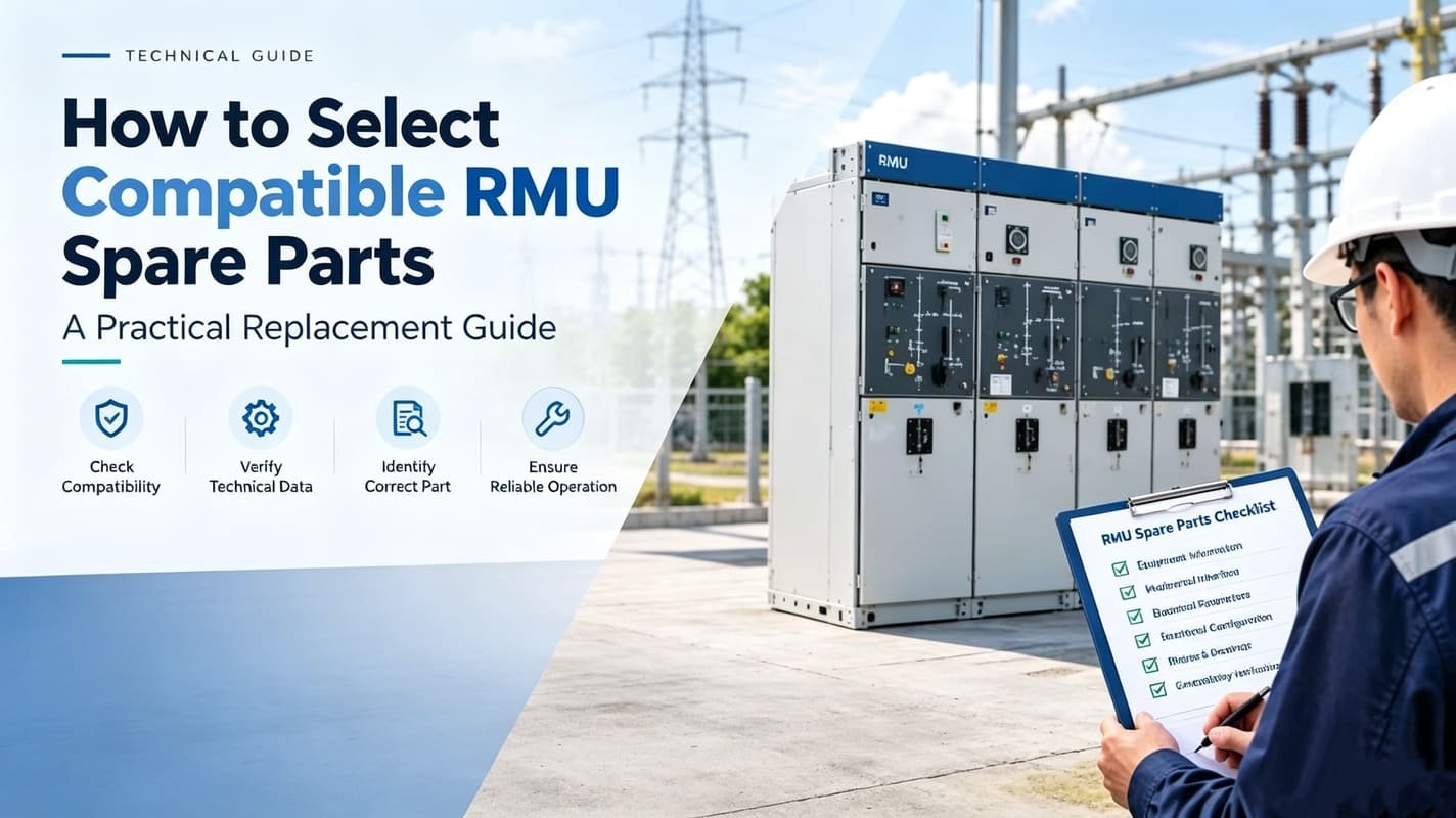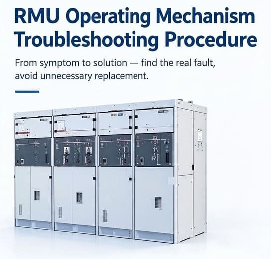

Selecting and replacing faulty components for a Ring Main Unit (RMU) is one of the most common yet error-prone tasks in medium-voltage switchgear maintenance. Many maintenance teams, EPC contractors, and electrical procurement teams mistakenly replace RMU spare parts based only on appearance, part name, or old part numbers. This practice frequently leads to mechanical mismatches, electrical parameter conflicts, incorrect position feedback, SCADA signal errors, and even dangerous switching failures.
Choosing compatible RMU spare parts requires strict verification of mechanical interfaces, electrical specifications, functional logic, and interlocking compatibility. For ageing MV switchgear fleets with missing original documentation or discontinued factory components, accurate aftermarket part selection directly reduces unplanned downtime, repeated modification work, and operational safety risks.
This practical engineering guide explains how to verify RMU spare part compatibility using field-proven technical standards — instead of relying on brand names, product photos, or outdated part data.
Compatibility Notice: Brand names and product family references in this article are used solely for equipment identification and technical matching. Aftermarket compatible RMU spare parts are not original manufacturer parts. Final compatibility must always be confirmed against the installed RMU configuration, functional modules, and official technical documentation.
What Are Compatible RMU Spare Parts?
A fully compatible RMU spare part refers to an aftermarket replacement component that perfectly matches the existing switchgear’s mechanical structure, electrical parameters, functional logic, and safety interlocking requirements. It must restore full original equipment performance without on-site modification.
Complete RMU spare part compatibility covers four core dimensions:
- Mechanical compatibility: mounting dimensions, hole positions, shaft geometry, operating angle, linkage stroke, and mechanical stop structure
- Electrical compatibility: control voltage, AC/DC type, motor power, auxiliary contact quantity, contact logic, and terminal wiring sequence
- Functional compatibility: consistent switching logic, closing/opening characteristics, and position feedback functions
- Interlocking & installation compatibility: mechanical interlock matching, compartment installation fit, and safety operation restrictions
Even two visually identical RMU operating mechanisms may differ in shaft offset, mounting hole layout, auxiliary contact arrangement, or switching travel. The same mismatch risk applies to auxiliary switches, position indicators, control coils, and SF6 monitoring devices. Most mainstream switchgear manufacturers, including Siemens, require full equipment data before approving spare part replacement, proving that appearance similarity never equals compatibility.
The correct verification question is never “Does this part look the same?” — it is “Does this spare part fully match the mechanical, electrical, and functional requirements of your installed RMU?”
1. Start Verification From the RMU Nameplate (Critical for Old Switchgear)
The first step in accurate RMU spare part selection is complete equipment identification. For ageing switchgear that lacks original manuals and factory files, the nameplate is the most reliable technical reference.
Record all available nameplate information:
- Equipment manufacturer / product family
- Exact model and type designation
- Unique serial number
- Rated voltage and rated current
- Manufacturing year (if marked)
- Functional module type
- Circuit configuration (incoming / outgoing / loop)
Do not assume identical compatibility within the same product family. Different production batches, generation upgrades, control configurations, and functional module combinations often require completely different RMU replacement parts.
2. Confirm the Exact Functional Module (Avoid 80% of Selection Errors)
The most frequent cause of wrong RMU spare part replacement is identifying only the cabinet type while ignoring the compartment’s functional module. Each RMU functional unit has independent mechanism structures and control logic, and parts cannot be cross-used.
Common RMU functional modules include:
- Load break switch module
- Earthing switch module
- Fuse-switch combination module
- Circuit breaker module
- Incoming feeder unit
- Outgoing feeder unit
An operating mechanism suitable for a load switch compartment may fail interlocking or travel matching when installed on an earthing switch module. Professional spare part suppliers must confirm both cabinet model and compartment function before recommending replacements.
3. Strictly Compare Mechanical Interface Parameters
Mechanical compatibility determines whether the RMU part can be installed and operated correctly. Minor dimensional deviations will cause jamming, incomplete switching, failed latching, and position indication errors.
Before ordering replacement mechanical components or operating mechanisms, verify all key interface items:
- Mounting hole position and spacing
- Overall external dimensions
- Shaft diameter, shaft height and offset position
- Operating direction and switching angle
- Linkage structure and stroke length
- Fixing and locking method
- Mechanical stop limiting structure
- Safety interlock arrangement
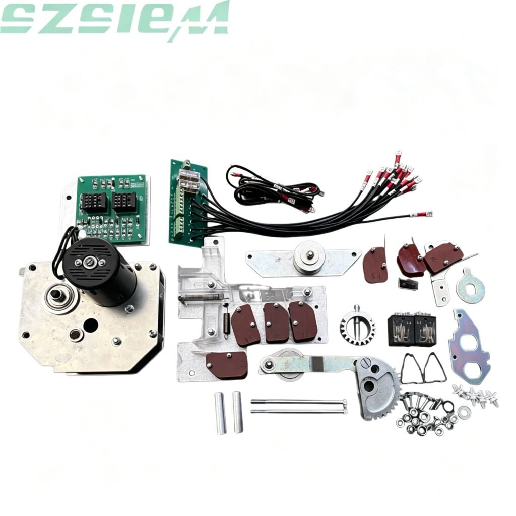
Never modify mounting holes or shafts to force-fit uncertain parts. On-site modification will void safety consistency and may cause serious switching failures. Professional interface verification is mandatory before production and installation, especially for core RMU operating mechanism replacements.
For full field procedures and fault diagnosis, refer to our professional guide for RMU operating mechanism replacement.
4. Verify Full Electrical Compatibility (Avoid SCADA & Control Faults)
Mechanical fitting does not guarantee electrical compatibility. Mismatched electrical parameters will lead to motor burnout, remote operation failure, incorrect feedback signals, and SCADA system alarm errors — even if the part fits perfectly physically.
For motorized and electrically controlled RMU spare parts, confirm:
- Exact control voltage value
- AC or DC power supply type
- Motor rated power and starting current
- Auxiliary contact quantity and normally open/closed logic
- Terminal arrangement and wiring sequence
- Real-time position feedback signal requirements
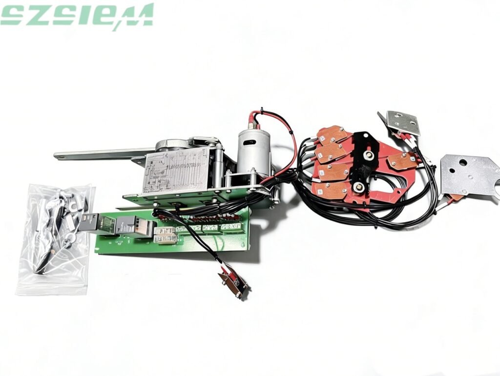
Many field failures occur after replacing mechanically matched but electrically incompatible parts. Wrong auxiliary contact configurations directly cause remote status disorder, which severely affects distribution automation system operation.
5. Reference Original Part Number — But Never Rely On It Alone
The original factory part number is a valuable reference, but it cannot be used as the sole compatibility basis. Long-term operating RMU equipment often undergoes iteration and modification, making old part numbers invalid.
Common part number invalid situations:
- Original parts discontinued and upgraded
- Factory configuration updated in new batches
- Previous on-site maintenance modifications
- Different generation cabinets using the same old part number
The most accurate identification method combines part number + nameplate data + physical photos + technical parameters. Complete information allows suppliers to perform cross-verified engineering confirmation.
6. Take Standardized Photos for Accurate Compatibility Verification
Clear and complete field photos effectively eliminate judgment errors in RMU spare part matching. Single-angle appearance photos are insufficient for technical verification.
For professional compatibility assessment, capture the following images:
- Full RMU cabinet front view
- Clear nameplate photo
- Close-up of the faulty component
- Component mounting position and installation space
- Terminal connection and wiring layout
- Operating shaft and linkage structure
- Part number label on original component
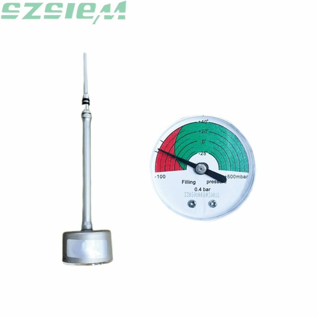
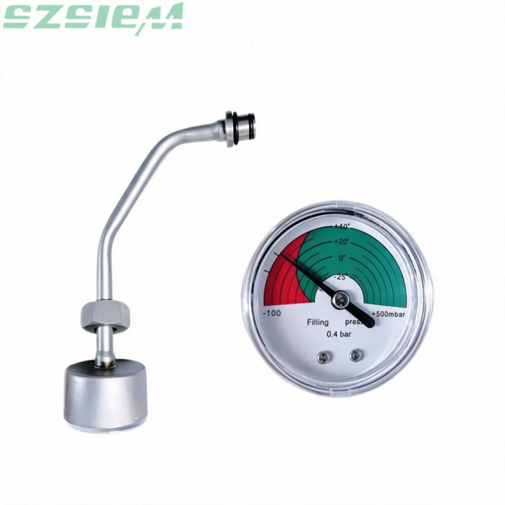
For precision accessories such as SF6 density monitors, include pressure range, connection thread type, dial parameters, and equipment operating environment. Accurate SF6 density gauge replacement relies on full parameter matching; appearance similarity cannot replace technical specification verification.
7. Diagnose Root Failure Cause to Avoid Blind Replacement
Symptoms do not always correspond directly to faulty components. Accurate fault diagnosis avoids unnecessary part replacement and repeated downtime.
Common field symptoms and corresponding faulty causes:
- RMU cannot close: mechanism jamming, linkage deformation, or interlock misalignment
- Remote operation failure: motor damage, control voltage mismatch, wiring error, or faulty auxiliary contacts
- Wrong position signal: auxiliary switch failure or position indicator deviation
- Heavy manual operating force: mechanical wear, internal contamination, or component misalignment
- Unstable SF6 readings: gauge aging, connection leakage, or instrument failure
- Frequent control tripping: electrical circuit short circuit or component aging
If the fault originates from wiring or power supply issues, replacing the operating mechanism will not solve the problem.
8. Choose Between Single Component Replacement or Full Assembly Replacement
Not every fault requires full mechanism replacement. Single damaged accessories such as auxiliary contacts can be replaced independently if the overall assembly remains mechanically intact.
Full assembly replacement is recommended in the following scenarios:
- Multiple internal components worn or damaged
- Excessive mechanical play in the operating mechanism
- Mounting base or fixing structure damaged
- Severe corrosion after long-term outdoor operation
- Unreliable position feedback signals
- Original single parts obsolete and unavailable
- Maintenance labor cost close to full assembly replacement cost
The core principle of RMU maintenance is to restore stable long-term operation with minimal lifecycle risk, rather than simply choosing the lowest-cost parts. Standardized spare part management also prevents future maintenance difficulties caused by obsolete components.
When individual components suffer cumulative wear, partial repairs may fail to guarantee long-term stability. A fully validated RMU electric operating mechanism features direct drop-in compatibility for RMU RM6 units, removing cabinet modifications and cutting commissioning time.
9. Complete RMU Spare Parts Verification Checklist (For Quotation & Ordering)
Use this checklist before requesting quotes to eliminate back-and-forth confirmation and reduce wrong delivery risks.
Equipment Basic Information
- Manufacturer / equipment family
- Model and type
- Serial number
- Rated voltage & current
- Functional module type
Replacement Part Information
- Accurate part name
- Original part number (if available)
- Replacement quantity
- Manual / motorized version
- Current component failure condition
Technical Parameter Information
- Control voltage (AC/DC)
- Auxiliary contact configuration
- Mechanical dimension data
- Mounting and interlock structure
- Terminal connection type
Visual Verification Materials
- Nameplate photo
- Faulty component close-up photo
- Installation environment photo
- Wiring and terminal photo
10. Key Questions to Ask Your RMU Spare Parts Supplier
Before placing orders, confirm these five critical points with your supplier to ensure compatibility:
- Can you verify compatibility with my exact RMU configuration? Avoid suppliers claiming “universal fit” without technical checking.
- Can you provide official dimensional drawings and interface data?
- Can you confirm all electrical parameters match my onsite system?
- Can you supply complete technical documentation, wiring diagrams and test reports?
- Is pre-production compatibility confirmation available?
The 5-Point Rule for Fast & Accurate RMU Spare Part Selection
For field maintenance and fast procurement, follow this standardized process:
Identify → Match → Verify → Document → Replace
- Identify: Confirm RMU nameplate, functional module and original component features
- Match: Compare full mechanical and electrical interface parameters
- Verify: Cross-check with drawings, photos, dimensions and technical data
- Document: Record replacement model, parameters and installation records
- Replace: Install only after full compatibility confirmation and follow safety procedures
FAQ — RMU Spare Parts Compatibility & Replacement
Q1: How do I confirm if an RMU spare part is compatible? A: Verify RMU model, functional module, mechanical interface dimensions, electrical parameters, auxiliary contact logic and installation interlock structure. Combine nameplate data, field photos and technical drawings for final confirmation.
Q2: Is aftermarket compatible RMU spare parts acceptable for official replacement? A: Yes. Aftermarket compatible components are widely used for ageing switchgear maintenance when mechanical, electrical and functional compatibility are fully verified. Appearance similarity alone is not a valid standard.
Q3: What information is mandatory for ordering RMU replacement parts? A: At minimum: RMU nameplate information, equipment model, functional module, clear component photos and control voltage parameters. An original part number is helpful but not mandatory.
Q4: Can the RMU operating mechanism be replaced separately? A: Most RMU operating mechanisms support independent replacement. Before replacement, confirm shaft travel, switching sequence, interlock logic and electrical control consistency.
Q5: How to completely avoid wrong RMU spare part orders? A: Avoid judging by product name or appearance only. Use a full checklist covering equipment identification, module function, mechanical dimensions, electrical parameters and onsite photos.
Conclusion
Selecting compatible RMU spare parts is a professional engineering verification process rather than a simple purchasing task. Accurate replacement depends on full equipment identification, failure diagnosis, mechanical & electrical parameter matching, and technical document verification.
This standardized selection method effectively reduces wrong-part orders, shortens maintenance downtime, and extends the service life of medium-voltage ring main units. For any RMU spare part replacement requirement, providing complete nameplate data, component photos and technical parameters allows professional suppliers to deliver fully compatible, field-tested replacement solutions.
If you are struggling to source verified compatible RMU spare parts including operating mechanisms, auxiliary switches and SF6 density gauges for your ring main unit, get in touch with our technical team for part‑matching support.