
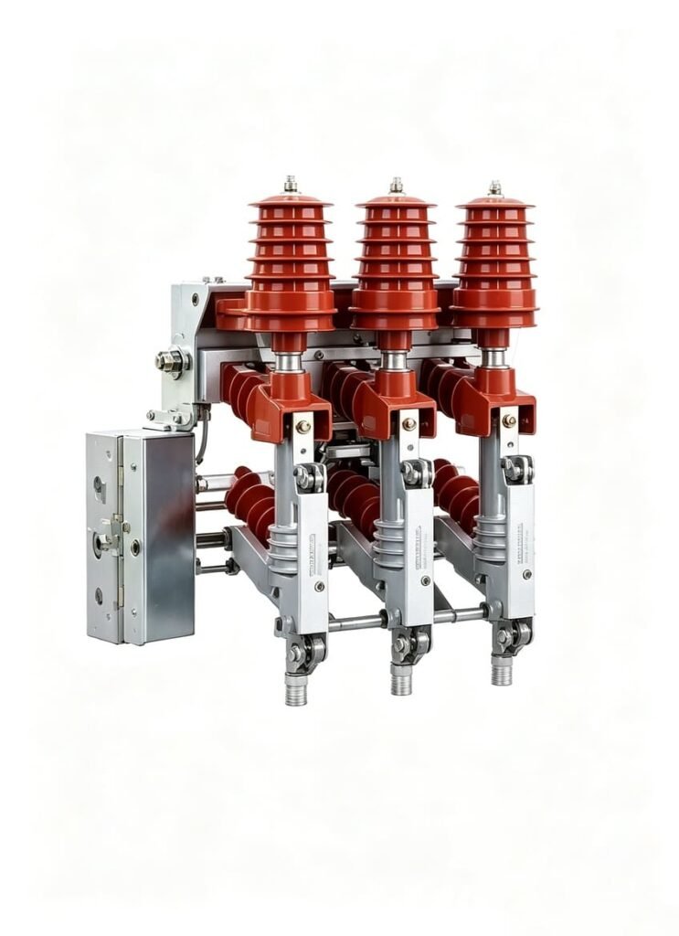
Medium-voltage load break switches (LBS) used in RMUs and metal-enclosed switchgear commonly develop mechanical, electrical or insulation faults after long-term field operation due to worn contacts, aging mechanisms, loose connections and degraded insulation.
When LBS issues occur — including difficult operation, closing failure, overheating and SF6 alarms — full switch replacement is unnecessary in most cases. This standardized load break switch troubleshooting guide covers typical symptoms, root causes, step-by-step inspections and IEC-compliant test procedures. It helps maintenance teams safely diagnose faults, avoid misjudgments, and source compatible LBS spare parts and operating mechanism components for compact distribution switchgear.
Safety note: MV switchgear troubleshooting must be performed by qualified personnel using the applicable isolation, lockout/tagout and test procedures. Never operate or inspect energized equipment unless the equipment and procedure specifically permit it.
Load Break Switch Troubleshooting: Start With the Symptom
Before removing covers or adjusting the mechanism, record the actual symptom accurately for targeted fault diagnosis. The same abnormal performance may stem from different components, so one-to-one cause assumption should be avoided.
| Observed problem | Possible area | First check |
| Switch fails to close | Mechanism/interlock | Position indication and mechanism |
| Switch fails to open | Mechanism/linkage | Operating shaft and spring system |
| Contact overheating | Contact/connection | Thermal inspection and resistance |
| High contact resistance | Contact assembly | Contact condition and test value |
| Excessive operating force | Mechanical system | Shaft, bearings and linkage |
| Abnormal operating noise | Mechanism | Loose or worn components |
| SF6 alarm | Gas/density monitoring | Density indication and leakage |
| Earthing operation blocked | Interlock | Operating sequence and interlock |
1. Load Break Switch Fails to Close
One of the most common load break switch faults is an incomplete or unsuccessful closing operation, which directly affects power distribution system switching safety.
Possible causes include:
- Mechanical obstruction
- Incorrect switch position
- Interlock not released
- Spring mechanism problem
- Misaligned operating shaft
- Worn latch or linkage
- Control circuit problem on motorized configurations
Start by confirming that the earthing switch and other mechanical interlocks are in the correct position. Three-position MV switchgear commonly uses interlocks to prevent incompatible switching operations. Technical documentation for MV switchgear shows that load break switch and earthing switch positions are mechanically linked to prevent incorrect operation.
If the mechanism moves but the contacts do not reach the correct position, inspect the transmission linkage and contact travel rather than repeatedly forcing the operating handle to avoid secondary component damage.
2. Load Break Switch Fails to Open
When an LBS fails to open, do not immediately assume that the primary contacts are damaged. Most open faults originate from mechanical transmission or interlock failures instead of contact damage.
Key inspection items:
- Operating handle or motor output
- Main operating shaft
- Spring charging and release mechanism
- Linkage movement
- Mechanical interlock
- Position indicator
A spring-operated LBS is designed to provide the required switching movement through stored mechanical energy. Different LBS mechanisms use spring energy and linkages to complete the switching operation independently of the operator’s final movement.
If the handle becomes unusually stiff before reaching the normal position, stop the operation and investigate the mechanism thoroughly to prevent shaft bending or linkage fracture.
3. Load Break Switch Contact Overheating
Load break switch contact overheating is a critical warning sign of increased electrical resistance in the current-carrying path, which may lead to equipment burnout and power outage risks if left unresolved.
Common causes include:
- Loose electrical connections
- Contact oxidation
- Contact wear
- Insufficient contact pressure
- Misalignment
- Damaged contact surfaces
A practical inspection can start with infrared thermal imaging while the equipment is operating under an appropriate load condition. After safe isolation, inspect the contact and connection points and perform contact resistance testing according to the equipment manufacturer’s procedure.
Do not judge a contact problem only by visual appearance. A contact can look intact while its electrical resistance has already exceeded the standard threshold.
4. High Contact Resistance
Load break switch contact resistance is a core technical indicator to evaluate the health status of the current-carrying path of medium-voltage switches.
High resistance may result from:
- Worn contact surfaces
- Oxidation or contamination
- Reduced contact pressure
- Loose connections
- Incorrect contact alignment
- Mechanical wear
The measured value should always be compared with the manufacturer’s specified limits and test method rather than applying one universal resistance value to every LBS design.
If resistance remains abnormal after connection checks, inspect the contact assembly and mechanical contact pressure, and replace worn contact parts in time if necessary.
5. Excessive Operating Force or Stiff Movement
A qualified load break switch should maintain smooth manual operation without increasing operating force during daily use.
If the mechanism becomes stiff, possible causes include:
- Dry or contaminated bearings
- Corrosion
- Foreign material accumulation
- Bent linkage
- Misaligned shaft
- Spring mechanism deterioration
- Mechanical interference
Repeatedly applying excessive force can damage the operating shaft or transmission components, leading to more costly repairs.
For medium voltage LBS troubleshooting, confirm the specific position of resistance first: handle, shaft, spring mechanism, linkage or primary switching assembly. This targeted method avoids unnecessary full LBS replacement and reduces maintenance costs.
6. Load Break Switch Operating Mechanism Fault
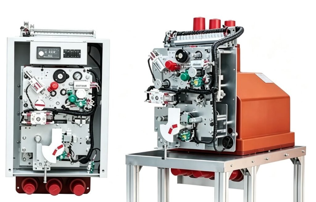
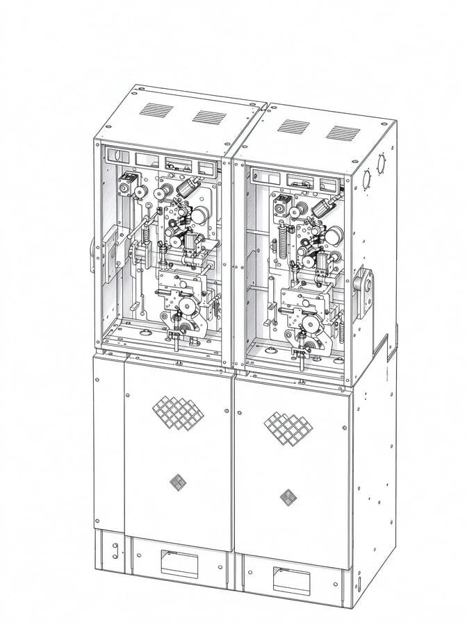
The load break switch operating mechanism is the core power component of motorized RMU and MV switchgear, directly determining switching stability and service life.
Typical symptoms include:
- Motor runs but switch does not change position
- Motor does not start
- Spring does not charge correctly
- Local operation works but remote operation fails
- Position indication does not correspond to the actual switch position
- Intermittent switching operation
For a motorized mechanism, divide the diagnosis into three core areas for efficient troubleshooting:
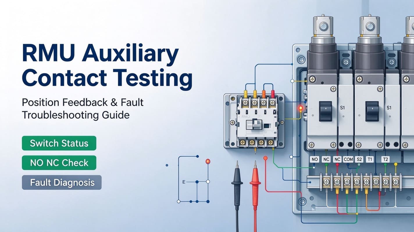
Control circuit: Check control voltage, fuses, auxiliary contacts and wiring for looseness or burnout. Motor/mechanical drive: Check motor output, gears, coupling and operating shaft for wear and deformation. Position feedback: Check auxiliary contacts and mechanical/electrical position indication for signal deviation.
Do not replace the motor simply because remote operation has failed. Most remote faults come from faulty control circuits or blocked mechanical transmission, which can be fixed with low-cost spare parts replacement.
7. Load Break Switch Interlock Problem
Interlock faults are common hidden troubles for LBS. A load break switch interlock problem can block normal switching operation even when the primary switch body is completely healthy.
Functional interlocks are designed to prevent unsafe operations:
- Closing the LBS while the earthing switch is engaged
- Earthing while the LBS is closed
- Opening an access compartment in an unsafe position
- Incorrect switching sequences
Three-position load break switches commonly adopt ON/OFF/EARTH operating arrangements with complete mechanical interlocking between switching functions.
If the mechanism appears mechanically blocked, verify the full switching sequence strictly before any adjustment. Never bypass an interlock to force the switch into position, which will cause serious safety accidents.
8. SF6 Load Break Switch Troubleshooting
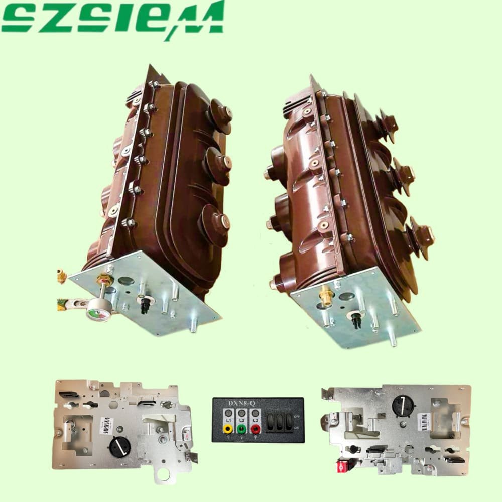
For SF6 load break switch widely used in modern RMUs, abnormal gas-density alarm is one of the most frequent troubleshooting items in daily operation.
Possible causes include:
- Actual SF6 gas leakage
- Temperature-related density indication deviation
- Faulty density gauge or relay
- Damaged sealing components
- Incorrect indication or wiring failure
Modern SF6 LBS designs are equipped with gas-pressure monitoring systems, which will lock electrical and manual operation when gas pressure falls below the safety threshold to avoid arcing faults.
A low-pressure indication must be inspected and resolved before putting the equipment back into service. For temperature-sensitive gas-density devices, judge the fault by combining ambient temperature, pressure curve and manufacturer’s alarm standards, instead of relying solely on real-time pressure readings.
9. Abnormal Noise During Switching
Grinding, clicking, knocking or irregular mechanical sounds during switching are early warning signals of component aging or damage, which cannot be ignored.
Possible causes include:
- Loose mechanism components
- Worn bearings
- Dry moving parts without lubrication
- Damaged linkage
- Spring mechanism wear
- Component misalignment
The most effective diagnostic method is to compare the current operating sound, action stroke and operating time with the manufacturer’s standard normal state. If obvious changes are found, stop operation and inspect the mechanism to prevent further damage.
10. When Should Load Break Switch Parts Be Replaced?
Not every LBS fault requires complete switch replacement. Most medium-voltage load break switch failures are caused by partial wearable components, which can be repaired by targeted spare parts replacement, greatly reducing equipment and construction costs.
Serviceable and replaceable LBS components include:
- Contact assembly
- Operating mechanism
- Spring
- Linkage
- Auxiliary switch
- Position indicator
- Density gauge or relay
- Sealing component
- Other compatible operating accessories
All replacement parts must be verified to match the original equipment configuration to ensure switching accuracy and operational safety.
For accurate spare part procurement and compatibility confirmation, prepare the following information:
- Rated voltage
- Rated current
- LBS model or type
- RMU/switchgear configuration
- Manual or motorized operation type
- Control voltage
- Photos of the existing mechanism
- Equipment nameplate information
Free Compatibility Check: If you are unsure whether to replace individual parts or the full LBS, send us your equipment parameters and mechanism photos. Our engineering team will provide professional matching suggestions and cost-effective replacement solutions.
Practical Load Break Switch Inspection Sequence
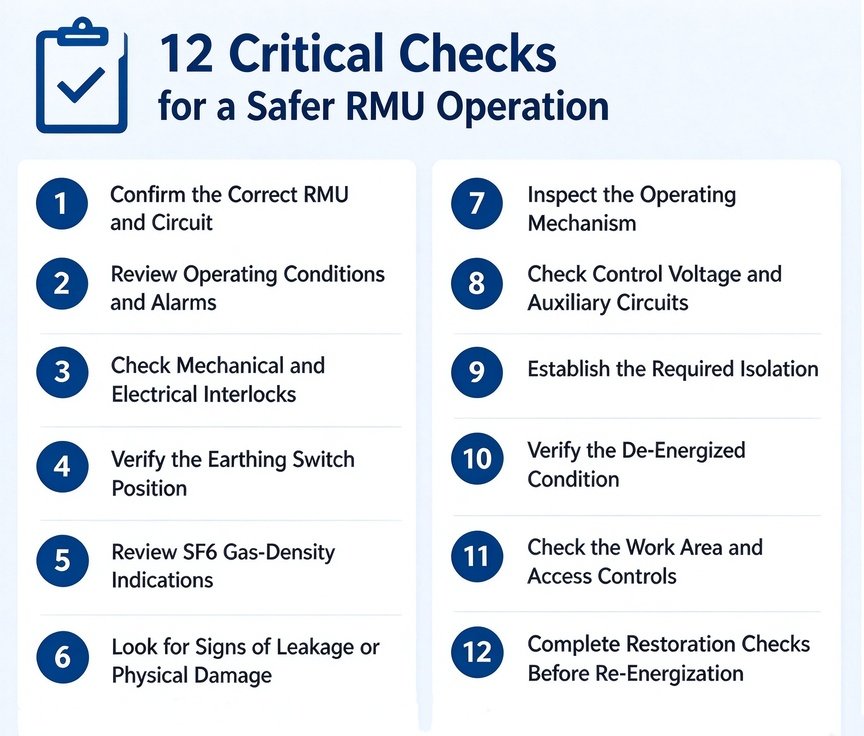
Follow this standardized troubleshooting sequence to avoid blind disassembly and unnecessary component replacement, compliant with IEC industry standards:
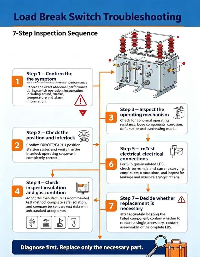
IEC 62271-103:2021 covers AC switches and switch-disconnectors above 1 kV and up to 52 kV, while IEC 62271-200:2021 covers AC metal-enclosed switchgear and controlgear in the same broad voltage range. All inspection and acceptance criteria shall prevail over official equipment documents and project actual requirements.
Load Break Switch Troubleshooting FAQ
Why does a load break switch fail to close?
The cause may be incorrect interlock status, mechanical obstruction, failed spring mechanism, shaft misalignment, worn linkage or control-circuit fault. Always check the standard operating sequence before forcing the mechanism to close.
Why does a load break switch overheat?
Common causes include increased contact resistance, loose wiring connections, contact surface oxidation, insufficient contact pressure and long-term worn contact surfaces.
How do you test load break switch contact resistance?
Adopt the low-resistance measurement method specified by the manufacturer, complete equipment power isolation and safety grounding, then test and compare the measured data with the official standard acceptance range.
Why is my load break switch difficult to operate?
Stiff operation usually results from mechanical corrosion, insufficient lubrication, bearing wear, component misalignment, foreign material blockage or aging operating mechanism.
What causes an SF6 load break switch alarm?
SF6 alarm triggers from abnormal gas density, tiny gas leakage, temperature-caused indication deviation, or faulty density monitoring gauges/relays. Verify the root cause thoroughly before restoring equipment operation.
Can the operating mechanism of a load break switch be replaced?
Most mainstream RMU and MV switchgear LBS operating mechanisms support independent replacement and retrofitting. It only needs to confirm the switch model, installation dimension, shaft arrangement, control voltage and operating sequence compatibility.
Need technical support? Send your LBS model and equipment photos to our team for one-stop spare part matching and replacement guidance.
Need Help With a Load Break Switch Replacement?
If your load break switch has switching failure, abnormal contact temperature, high contact resistance or mechanism damage, full equipment replacement is usually unnecessary and costly. We provide matched, high-quality medium-voltage switching components and compatible replacement operating mechanisms for most mainstream RMU and compact switchgear configurations.
For accurate compatibility check and customized solutions, please send us the following information:
LBS/RMU model + rated voltage + rated current + control voltage + existing mechanism photos.
Our professional engineering team will review your equipment configuration within 24 hours and recommend the most suitable spare part replacement or retrofit solution to help you save maintenance time and cost.
Request a Load Break Switch Compatibility Check now →