
Before energizing a medium-voltage ring main unit (RMU), engineers must verify proper installation, functional operating mechanisms, and completed electrical and control checks.
Uncaught interlock faults, incorrect auxiliary contact wiring or abnormal insulation readings cause commissioning delays and serious safety risks.
This guide covers essential pre-energization RMU commissioning tests: mechanical checks, insulation resistance testing, earthing switch verification, control circuit testing and SF6 density inspection, plus common site faults and troubleshooting.
Test scope varies with RMU design, rated voltage, insulation type, OEM instructions and project specs. Always follow approved procedures and acceptance criteria for your unit.
Need support for RMU commissioning, spare parts or custom project consultation?
Our medium-voltage switchgear engineers can assist with your RMU site testing & component replacement.
1. What Are RMU Commissioning Tests?
RMU commissioning tests are on-site inspections and functional checks after installation, before energization.
Purpose: Confirm correct assembly, safe connections and operational readiness under project conditions.
Typical scope:
- Visual & mechanical inspection
- Mechanism and interlock verification
- Earthing switch functional test
- Insulation resistance test
- Main circuit inspection
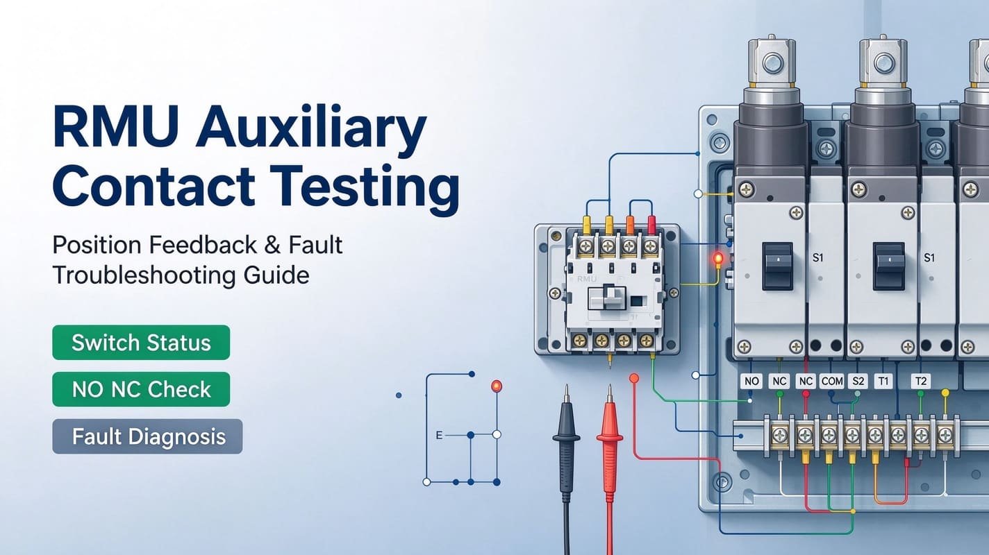
- Auxiliary contact & control circuit test
- Local / remote operation test (if fitted)
- SF6 density inspection (gas-insulated RMUs only)
- Protection, metering & communication checks (if applicable)
Factory Tests vs Site Commissioning
Factory routine tests are completed by manufacturers before shipment. Site commissioning checks for transit damage, correct installation and proper on-site function.
Site commissioning does not require repeating all factory tests. Scope follows project specs, standards and OEM manuals.
2. Pre-Commissioning: Visual & Mechanical Inspection
Complete these before electrical testing.
2.1 RMU Installation Check
- Cross-check model, rated voltage, rated current and configuration against approved drawings
- Verify nameplate and labels
- Inspect enclosure for damage, corrosion or missing parts
- Confirm secure mounting
- Check cable entry, supports and termination compartments
- Validate main earthing per design
- Match cable/control wiring labels with schematics
- Remove tools, packaging and debris from compartments
Cable terminations require extra attention. Poor connections or insufficient clearances reduce switchgear reliability and safety.
2.2 Operating Mechanism Inspection
- Inspect for damage, loose fasteners or obstructions
- Confirm operating handle inserts properly and completes full operating sequence
- Do not force stiff mechanisms; resolve issues before continuing
- For motorised RMUs: inspect motor, linkages, wiring and auxiliary components
3. Mechanical Interlock Test
Interlocks prevent unsafe switching sequences and vary by manufacturer. This test is critical before energization.
Checks:
- Confirm load break switch, CB and earthing switch initial positions
- Handle only inserts/operates under permitted conditions
- Earthing switch cannot close when main circuit is live
- Main switch cannot operate with earthing switch closed
- Verify door/panel interlocks
- Position indicators match actual mechanism status
Never bypass interlocks to complete tests.
Common Fault: Operating handle cannot be inserted
- Confirm switch and earthing switch actual positions
- Check mechanism state for handle insertion
- Inspect interlock linkage for blockage or misalignment
- Confirm full operating stroke completed
- Compare indicator with real mechanical position
Stop work if unresolved and follow OEM procedures. Do not modify interlocks. See our RMU Mechanical Interlock Working Principle and Troubleshooting Guide.
4. Earthing Switch Test
The earthing switch earths the circuit within design limits. Verify mechanical operation and position indication.
Checklist:
- Inspect earthing switch mechanism
- Confirm open/closed position indication
- Validate sequence matches interlock logic
- Prevent operation under prohibited conditions
- Check earthing connections against drawings
- Test auxiliary contacts for remote monitoring (if fitted)
Conduct tests under approved isolation procedures. Indication alone does not prove safe earthing or isolation.
5. Insulation Resistance Test
This test assesses insulation integrity, phase-earth or phase-phase as required. Select test voltage per OEM and project requirements.
5.1 Pre-test
- Isolate equipment and apply safety controls
- Confirm circuit fully de-energized
- Disconnect or protect sensitive electronics
- Confirm test points; record unit ID and ambient conditions
5.2 During test Measure:
- Phase to earth
- Phase to phase
- Other specified insulation paths
Record readings, test voltage, duration, temperature and conditions.
5.3 Result evaluation
No universal pass/fail threshold. Acceptance criteria depend on design, insulation material, voltage, environment and specs.
Investigate low/unstable readings. Causes include moisture, contamination, insulation damage or incorrect test connections.
Important: Insulation resistance test is not equivalent to AC/DC dielectric withstand test and cannot replace cable tests. Do not apply high voltage unless OEM and procedure explicitly approve.
6. Main Circuit & Contact Resistance Checks
Where required, use a micro-ohmmeter to test connections and identify high resistance from poor joints or damaged contacts.
Test points:
- Main circuit joints
- Accessible busbar connections
- Cable terminations
- Switching contacts (where permitted)
Compare readings with OEM data, factory records or project criteria. Avoid generic resistance limits.
7. Auxiliary Contact & Control Circuit Testing
Auxiliary contacts send status signals for local indication, remote monitoring and interlocks. Faulty wiring can produce incorrect status feedback even with correct mechanical operation.
7.1 Auxiliary Contact Tests
- Cross-check wiring against schematics
- Confirm NO/NC configuration
- Test continuity for all switch positions
- Validate local and remote status feedback
- Check terminal and cable marking
7.2 Control Circuit Tests (Motorised RMUs)
- Control supply voltage
- Fuse / MCB health
- Relay operation
- Motor, command, interlock and feedback circuits
- Terminal connections
Common Fault: Local operation OK, wrong position on control room display
- Confirm actual mechanical switch position
- Compare with local indicator
- Check NO/NC auxiliary contact status
- Inspect wiring and terminals
- Trace feedback signal to RTU
- Verify control system signal logic
Do not replace the motor immediately. The fault is usually contacts, wiring, terminals or RTU configuration. See RMU Auxiliary Contact Testing Guide.
8. Local & Remote Operation Tests
For motorised / remotely operated RMUs, test functions per approved procedure.
Checklist:
- Local / remote open & close commands
- Local/remote selector switch
- Electrical interlocks
- Position feedback
- Alarm and fault signals
- Communication with RTU / SCADA
A successful motor operation does not validate the full remote control system. Verify command paths, interlocks, contacts, wiring and logic. See RMU Remote Control Troubleshooting Guide.
9. SF6 Gas Density Inspection (Gas-Insulated RMUs Only)
Skip for air-insulated or alternative-gas RMUs.
Check density monitoring system:
- Density gauge / relay condition
- Leakage or physical damage
- Density/pressure readings
- Alarm/lockout wiring (if fitted)
- OEM reference conditions
- Low-density alarms
Pressure vs Density
SF6 pressure changes with temperature. Use OEM temperature-compensated reference data. Density monitors compensate for temperature.
Common Fault: SF6 density alarm in cold weather
- Record ambient temperature and reading
- Compare with OEM limits
- Inspect density monitor and wiring
- Check for gas leaks
- Verify alarm contact and circuit
- Follow OEM corrective actions
Do not reset alarms blindly. Do not refill gas or adjust relays without authorization and approved procedures.
10. Protection, CT/VT & Project-Specific Tests
For RMUs fitted with protection relays, CTs, VTs or communication hardware:
- CT / VT ratio and polarity checks
- Secondary injection test
- Protection relay setting verification
- Trip circuit test
- Metering and alarm / communication validation
Qualified personnel must perform these tests per project specs.
11. Commissioning Test Record Template
For documentation only; not universal acceptance criteria.
| Test / Inspection | Recorded Result | Acceptance Reference | Status |
|---|---|---|---|
| Visual inspection | Installation & defects | Drawings / OEM instructions | Pass / Fail |
| Mechanical operation | Sequence & abnormal movement | OEM procedure | Pass / Fail |
| Mechanical interlock | Permitted / prohibited sequences | Interlock diagram | Pass / Fail |
| Earthing switch | Operation & position indication | Approved procedure | Pass / Fail |
| Insulation resistance | Voltage, duration, readings | OEM / project criteria | Pass / Fail |
| Contact resistance | Values & test points | OEM / project criteria | Pass / Fail |
| Auxiliary contacts | NO/NC state & feedback | Wiring diagram | Pass / Fail |
| Local/remote control | Command & feedback results | Schematic / specs | Pass / Fail |
| SF6 density inspection | Indication & alarms (if applicable) | OEM reference | Pass / Fail |
| Protection tests | Relay & trip results (if applicable) | Protection settings | Pass / Fail |
Record equipment ID, date, instrument calibration, ambient conditions, staff and corrective actions. Resolve non-compliant results and gain approval before proceeding.
12. Common Commissioning Problems & Troubleshooting
| Symptom | Possible Cause | Recommended Check |
|---|---|---|
| Operating handle cannot be inserted | Wrong switch position / jammed interlock | Check mechanism & interlock linkage |
| Earthing switch fails operation | Unmet interlock condition / mechanism fault | Verify sequence and mechanism |
| Low insulation resistance | Moisture, contamination, damaged insulation or wrong test setup | Inspect connections and insulation |
| Local OK, remote fails | Supply, wiring, relay or RTU fault | Trace command & feedback circuits |
| Incorrect position indication | Auxiliary contact or wiring fault | Check NO/NC and terminal wiring |
| SF6 density alarm | Low gas, temperature effect or faulty monitor | Cross-check OEM reference, inspect monitor |
Start troubleshooting with simple checks and follow OEM manuals. Never bypass interlocks or energize with unresolved critical defects.
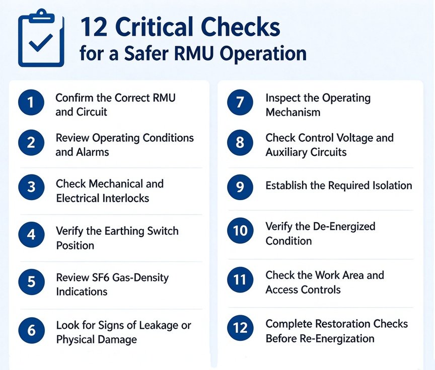
13. Final Pre-Energization Checklist Before energization:
- Installation matches approved drawings
- All mechanical checks completed
- Interlocks and earthing switch validated
- Insulation and contact resistance tests done
- Auxiliary contacts and control circuits checked
- Local/remote functions verified (if fitted)
- SF6 inspection complete (GIS RMUs)
- Protection and communication tests done (if required)
- Test records reviewed and accepted
- Defects resolved or formally assessed
- Temporary test gear and debris removed
- RMU ready for energization per switching plan
Energization requires authorized personnel and compliance with site safety rules.
14. FAQ: RMU Commissioning Tests
Q1. What tests are required before RMU energization?
Visual inspection, mechanical operation, interlock and earthing switch checks, insulation resistance and control circuit tests. Add SF6 density, contact resistance, protection and communication tests as needed.
Q2. Is insulation resistance test mandatory for all RMUs?
Requirements depend on RMU design, OEM instructions and project specs. Approved procedures define test points, voltage and acceptance criteria.
Q3. What is the difference between commissioning and factory routine tests?
Factory tests are pre-shipment. Site commissioning verifies installation integrity and on-site function.
Q4. How to test RMU mechanical interlocks?
Test permitted and prohibited switching sequences per OEM procedure. Validate mechanism positions, handle rules and indicators. Never force or bypass interlocks.
Q5. Does every RMU need SF6 density testing?
No. Only SF6 gas-insulated RMUs fitted with density monitors require this test.
Q6. RMU works locally but remote control fails. Why?
Possible causes: supply fault, bad relays, wrong auxiliary wiring, RTU configuration, communication error or unmet interlock conditions. Check command and feedback circuits systematically.
Conclusion
Complete RMU commissioning validates mechanical performance, insulation, interlocks, earthing and control systems. Use acceptance criteria matching your RMU model. Do not rely on generic limits without OEM and project requirements.
Check operating mechanisms, auxiliary contacts, earthing switches and wiring before energization to catch faults early.
Xizi Energy | RMU Components & Replacement Mechanisms
We supply medium-voltage switchgear spare parts for selected RMU models.
Share these details for compatibility review:
- RMU brand & model
- Rated voltage and configuration
- Photos of operating mechanism
- Control voltage (motorised units)
- Nameplate or wiring diagram