7S-QM-DC48V Electric Operating Mechanism | SM6 QM-Compatible Replacement

creative underline.png

Features:

The SM6 QM Electric Operating Mechanism is an aftermarket-compatible motorized operating assembly developed for selected SM6-QM medium-voltage switchgear configurations.
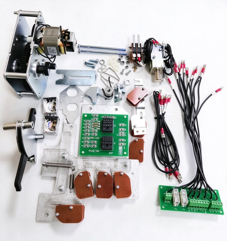
It is designed for applications where an existing manually operated mechanism needs to be replaced, motorized or upgraded for remote electrical operation. The assembly combines the drive motor, mechanical transmission components, auxiliary microswitches, control wiring, mounting hardware and related operating components into one integrated mechanism package.
For maintenance contractors, switchgear manufacturers and power distribution projects, this approach can reduce the need to replace the complete RMU cabinet when only the operating mechanism requires upgrading.
Important Note: Compatibility must be verified against the actual switchgear configuration, mechanism version, mounting dimensions, control voltage and auxiliary circuit before ordering.
creative underline.png

Description:

SM6 QM Operating Mechanism for Replacement & Retrofit

The operating mechanism is one of the most frequently operated mechanical assemblies inside medium-voltage switchgear. Mechanical wear, spring fatigue, damaged microswitches, motor failure or aging wiring can eventually affect reliable switching operation. Learn more about common faults and fixes in our RMU operating mechanism troubleshooting guide.
For existing SM6-QM installations, replacing the complete switchgear may be unnecessary when the main problem is concentrated in the operating mechanism.
This SM6 QM motorized operating mechanism provides an alternative solution for:
  • Operating mechanism replacement
  • Manual-to-electric motorization
  • RMU automation retrofit
  • Remote switching applications
  • Aging mechanism refurbishment
  • Switchgear maintenance projects
  • Distribution automation upgrades
The assembly is supplied with the main mechanical and electrical components required for the configured installation, helping engineers simplify spare-parts sourcing and field replacement.

Key Features of the SM6 QM Motorized Mechanism

1. Integrated Motor Drive Assembly

The mechanism uses an electric motor to provide the mechanical driving force required for the configured switching operation.
The motor drive is integrated with the transmission mechanism rather than being supplied as a standalone motor. This allows the complete operating assembly to be evaluated as a mechanical and electrical system.

2. Designed for SM6-QM Compatibility

The mechanism is developed around the mechanical structure and operating requirements of selected SM6-QM switchgear configurations.
Important matching points include:
  • Mounting position
  • Drive shaft arrangement
  • Operating direction
  • Mechanical transmission
  • Auxiliary microswitch positions
  • Control wiring
  • Interlocking arrangement
  • Control voltage
Because SM6 equipment can vary by generation, functional unit and configuration, the exact interface should always be confirmed before shipment.

3. Remote Electrical Operation

After correct installation and integration with the appropriate control circuit, the motorized mechanism can allow electrical operation from a local control panel or distribution automation system.
This makes the mechanism suitable for projects involving:
  • Remote switch operation
  • Distribution automation
  • RTU/DTU integration
  • SCADA monitoring
  • Unattended substations
  • Smart distribution networks
The auxiliary contacts and wiring configuration should be matched to the customer’s control system requirements.

4. Manual Emergency Operation

A motorized switchgear mechanism should not eliminate the possibility of local mechanical operation.
The pictured assembly incorporates mechanical operating components that can support manual intervention according to the final configuration.
This is useful during:
  • Commissioning
  • Maintenance
  • Control-power failure
  • Troubleshooting
  • Local switching operations
The exact manual operating procedure must follow the applicable switchgear design and site safety procedure.

SM6 QM Operating Mechanism Replacement

When replacing an existing operating mechanism, selecting a component only by the switchgear model is not sufficient.
Engineers should check the following parameters before purchasing:

Mechanical Compatibility

Verify:
  • Existing mechanism type
  • Mounting hole position
  • Shaft diameter and position
  • Operating direction
  • Transmission linkage
  • Mechanism dimensions
  • Available installation space

Electrical Compatibility

Confirm:
  • Motor control voltage
  • Motor power requirements
  • Auxiliary contact arrangement
  • Terminal configuration
  • Remote/local control circuit
  • Interlocking logic

Switchgear Configuration

The QM functional unit should also be confirmed from the equipment nameplate and existing cabinet documentation.
This is particularly important for older switchgear because mechanism versions and control circuits can differ between production generations.

SM6 QM Motorization Retrofit

For an existing manually operated switchgear installation, the main advantage of a motorized operating mechanism retrofit is that it can add electrical operating capability without replacing the complete switchgear cabinet, provided the mechanical and electrical interfaces are suitable. See our compatible Schneider medium voltage switchgear 7S SM6 KGG-S unit for matching retrofit hardware.
A typical retrofit project includes:
Existing manual mechanism → Compatibility inspection → Motorized mechanism installation → Secondary wiring → Interlock verification → Electrical operation test → Remote signal verification
Before installation, the original mechanism should be photographed and measured. The control voltage should also be confirmed independently from the switchgear’s rated voltage.
Key Distinction: 12 kV / 24 kV refers to the switchgear voltage class, while DC24V / DC48V / other values refer to the operating/control circuit. These are different parameters and must not be confused.

Typical Applications

The SM6 QM motorized operating mechanism can be considered for the following applications when compatibility has been confirmed. Check our full overview on where RMUs are commonly used across power distribution projects.

Medium-Voltage Distribution Networks

Used for motorization and replacement projects in distribution substations where remote switching is required.

Industrial Power Distribution

Suitable for industrial facilities that need to reduce manual switching operations and integrate MV switchgear into centralized control systems.

Renewable Energy Projects

Motorized RMU mechanisms can be used in photovoltaic, battery energy storage and other distributed-energy projects where remote distribution equipment operation is required.

Existing RMU Retrofit

For aging manually operated equipment, replacing the operating mechanism can be an alternative to replacing the complete RMU, depending on equipment condition and compatibility.

Switchgear Maintenance

The complete assembly can also be used as a replacement spare part for maintenance contractors and switchgear service companies.

Technical Specifications

Parameter
Specification
Product Type
Electric / Motorized Operating Mechanism
Model
7S-QM-DC48V
Application
Selected SM6-QM switchgear configurations
Control Voltage
DC48V
Operating Mode
Electric operation + manual operation, configuration dependent
Drive System
Motor-driven mechanical transmission
Auxiliary Components
Microswitches / auxiliary signal components
Wiring
Pre-assembled control wiring, configuration dependent
Installation
Replacement / retrofit
Application Voltage Class
Subject to actual switchgear configuration
Remote Control
Available when integrated with suitable control circuit
SCADA/RTU Integration
Supported through compatible secondary control interface
Customization
Control circuit and mechanical configuration can be confirmed according to project requirements
Important Specification Note: The control voltage shown above refers to the mechanism’s electrical supply, not the rated voltage of the medium-voltage switchgear. Final specifications should be confirmed against the actual mechanism configuration and project drawing before production.

What Should Be Checked Before Ordering?

For an accurate SM6 QM operating mechanism replacement, we recommend providing:
  • Switchgear nameplate photo
  • Original operating mechanism photo
  • Front and side installation photos
  • Existing motor or mechanism identification
  • Control voltage
  • Terminal/wiring photo
  • Mounting dimensions if available
  • Required remote-control functions
  • Auxiliary contact requirements
  • Switchgear production year or serial information
Our engineering team can then compare the mechanical interface and electrical configuration before quotation.
This configuration-check process is especially important for retrofit projects because apparently similar MV switchgear can use different mechanism arrangements.

Why Use a Complete Motorized Mechanism Assembly?

A common problem with switchgear maintenance is purchasing individual components without checking how they interact with the complete operating system.
A motorized operating mechanism consists of more than a motor. Reliable operation depends on the relationship between:
Motor + transmission + spring mechanism + microswitches + wiring + interlocking + control circuit
Replacing only a failed motor may not solve problems caused by worn mechanical parts, incorrect travel, damaged auxiliary contacts or aging wiring.
The complete assembly shown in the product image provides a more practical option when the existing mechanism requires comprehensive replacement or motorization.

FAQ

What is an SM6 QM operating mechanism?

An SM6 QM operating mechanism is the mechanical assembly responsible for operating the switching function of a compatible QM functional unit. A motorized version adds electrical drive capability for remote or automated operation.

Can the SM6 QM mechanism be replaced?

Yes, a compatible replacement mechanism can be used for selected SM6-QM configurations. However, the mechanism version, mounting interface, shaft arrangement, control voltage and auxiliary circuits should be verified before ordering.

Can a manual SM6 QM switch be motorized?

Selected configurations can be upgraded with a motorized operating mechanism. The feasibility depends on the original mechanism, cabinet configuration and required electrical control circuit.

Is this an original Schneider Electric mechanism?

No. This product is an independently manufactured aftermarket-compatible component. It is not an original Schneider Electric OEM product and is not authorized, endorsed or licensed by Schneider Electric.

What control voltage does the 7S-QM-DC48V use?

The pictured 7S-QM-DC48V configuration is designed for a DC48V control supply. Other configurations should be confirmed separately according to the project requirements.

Can the mechanism connect to SCADA?

Yes, when the appropriate auxiliary contacts and control circuit are configured, the motorized mechanism can be integrated into RTU, DTU or SCADA-based distribution automation systems.

How can I confirm compatibility?

Send us the switchgear nameplate, original mechanism photos, wiring/terminal photos and control voltage. Mounting dimensions and mechanism identification information are also useful for engineering verification.

Trademark & Compatibility Notice

SM6 and Schneider Electric are trademarks of their respective owners. References to SM6 or SM6-QM on this page are used solely to identify the switchgear platform for compatibility and replacement purposes.
This product is an independently manufactured aftermarket-compatible operating mechanism. It is not an original Schneider Electric product and is not produced, authorized, endorsed, sponsored or licensed by Schneider Electric.
Actual compatibility must be confirmed against the installed equipment before purchase or installation.

Get A Instant Quote Now!