
Trademark & Compatibility Notice: ABB and SafeRing are trademarks of ABB Group. These names are used only to identify the applicable switchgear platform and compatibility requirements. Xizi Energy is an independent supplier of medium‑voltage switchgear components and is not affiliated with, authorized by, or endorsed by ABB.
No ABB logos or official product imagery are reproduced on this page. All technical descriptions are independently compiled for reference only. Any replacement component should be verified against the actual switchgear configuration before installation.
From our field‑support experience with SafeRing RMU spare‑part projects, many motor‑failure service calls turn out to be control‑circuit or mechanical‑binding issues instead of defective motorized mechanisms. A motorized operating mechanism enables an RMU for electrical switching instead of full manual operation. Within distribution automation systems, it supports remote control via control panels, RTU or SCADA.
Still, non‑functional motorized mechanisms do not always point to a broken motor. For engineers troubleshooting an ABB SafeRing motorized operating mechanism, typical root causes cover incorrect control voltage, blown fuses, loose wiring, faulty auxiliary contacts, mechanical resistance, interlocking or other control‑circuit defects.
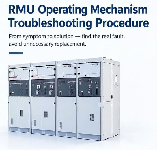
This practical guide walks through step‑by‑step troubleshooting, control‑voltage verification, evaluation for SafeRing motor mechanism replacement, and key technical data required to source a compatible aftermarket component.
What Is a Motorized Operating Mechanism?
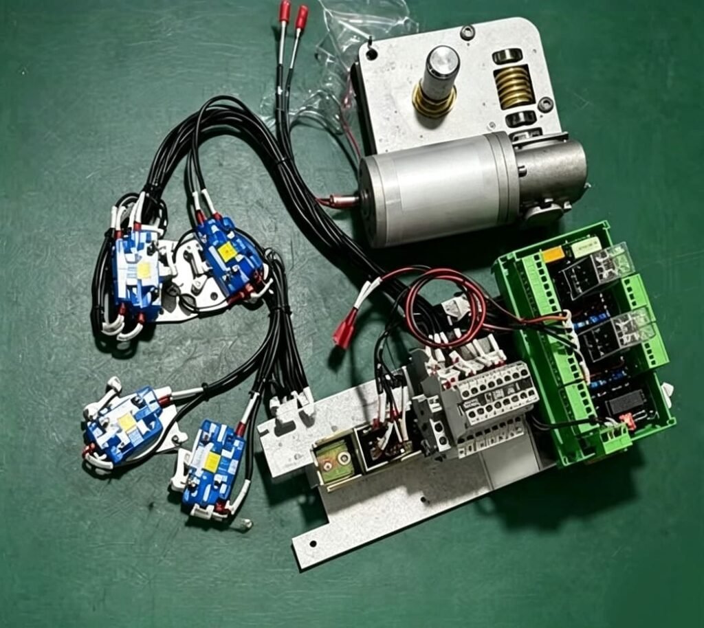
A motorized operating mechanism is an electromechanical assembly for electrically driving or charging switching units in medium‑voltage switchgear.
On SafeRing / SafePlus platforms, motor operation applies to load‑break switches, circuit‑breakers and switch‑fuse combinations, subject to module and site configuration. Retrofitting a motor unit onto manual‑operation RMUs delivers these core capabilities:
- Local electrical operation
- Remote opening and closing
- Distribution automation
- SCADA integration
- Remote feeder switching
- Automatic switching sequences
- Maintenance & retrofit projects
Treat the motorized mechanism as part of the full secondary control system, not merely an isolated electric motor.
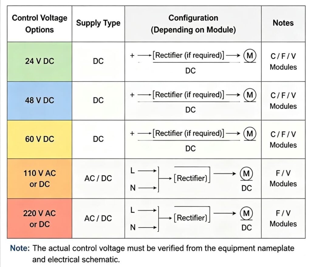
SafeRing Motor Control Voltage: What Should Be Checked?
Failed motor operation very often traces back to control‑voltage issues.
Per ABB documentation, SafeRing motor options include 24 V, 48 V, 60 V, 110 V and 220 V. Certain 110 VAC / 220 VAC variants integrate an internal rectifier to supply DC power for the motor. These voltage ratings are not interchangeable.
Before ordering a replacement mechanism, cross‑check these items:
- Switchgear nameplate
- Existing motor / mechanism label
- Electrical schematic
- Control power supply
- AC or DC configuration
- Fuse and protection arrangement
- Control terminal identification
Compare nominal drawing voltage against real‑world measured voltage at mechanism terminals.
Why Does the Motor Have Voltage but Not Run?
Good voltage readings at the control cabinet do not guarantee sufficient operating voltage under load. Likely causes:
- Voltage drop during motor starting
- Loose terminal connection
- Open control circuit
- Damaged relay contact
- Blown fuse
- Faulty limit switch
- Mechanical interlock
- Excessive mechanical resistance
- Motor winding or internal component failure
Always trace the full control path instead of directly replacing the mechanism.
SafeRing Motor Troubleshooting: Step‑by‑Step Inspection
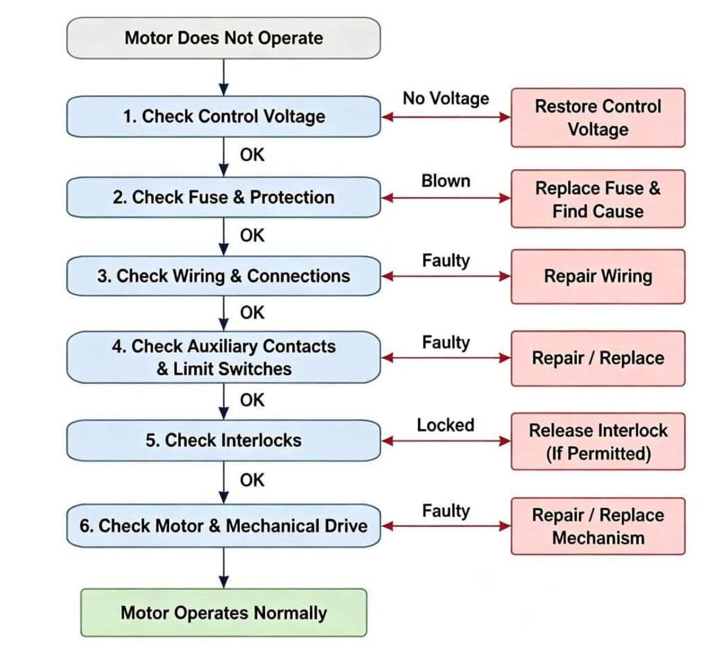
1. Confirm the Control Supply
Verify rated control voltage arrives at designated terminals per electrical schematics. If voltage reads fine with no load but collapses when issuing motor commands, troubleshoot power supply, wiring, terminals and protective devices. Do not rely purely on nominal 110 V / 220 V system labels.
2. Check the Fuse and Protection Circuit
Motor starting current exceeds normal running current. Never keep replacing blown fuses without root‑cause analysis. Investigate:
- Short circuit
- Damaged wiring
- Motor winding fault
- Mechanical seizure
- Incorrect protection rating
- Excessive starting load
A repeatedly blown fuse is a symptom, not a fault source.
3. Inspect Control Wiring
Loose or degraded wiring triggers intermittent failures, especially on aged units and retrofit RMUs.
Check terminal tightness, connector condition, cable continuity, overheating marks, damaged insulation, incorrect terminations and relay contacts. For retrofits, follow schematics rather than wire‑color assumptions.
4. Check Auxiliary Contacts and Limit Switches
Auxiliary contacts and limit switches handle position feedback and motor stop logic. Two frequent failure modes:
- Mechanism refuses to operate
- Mechanism works mechanically, yet remote SCADA shows incorrect position status
Inspect auxiliary contacts, limit switches, mechanical actuators, feedback terminals, control wiring and PLC/RTU input signals. Feedback errors are not motor faults.
5. Inspect the Mechanical Drive
Abnormal hum, slow movement or incomplete operation signals mechanical overload. Root causes:
- Worn gears
- Misalignment
- Damaged linkage
- Excessive friction
- Spring mechanism problems
- Corrosion
- Foreign material
- Deformed mechanical components
Do not force operation or bypass sequences to overcome mechanical resistance.
6. Verify Interlocking Conditions
Mechanical and electrical interlocks block unsafe switching sequences. Healthy motors may still refuse commands due to interlock logic.
Never permanently bypass a safety interlock to force motor operation.
When Is a SafeRing Operating Mechanism Replacement Necessary?
Fuse, relay, auxiliary‑switch or loose‑terminal faults do not require full mechanism replacement.
Prioritize a SafeRing operating mechanism replacement when you observe:
- Failed motor
- Damaged gears / broken linkage
- Severe mechanical wear & excessive play
- Burned internal components
- Operation‑impairing corrosion
- Repeated mechanism failures
- Damaged mounting interface
- Economically unreparable internal damage
For older switchgear, fitting a complete compatible aftermarket unit is often more practical than rebuilding multiple worn‑out parts. Compatibility must be validated against site hardware.
If you need technical support confirming compatibility for your SafeRing mechanism replacement, send us nameplate & mechanism photos for our engineering review.
Can a SafeRing Motor Mechanism Be Retrofitted?
Selected SafeRing / SafePlus modules support motor‑coil retrofits. Retrofit is an engineering compatibility project rather than simple plug‑and‑play installation.
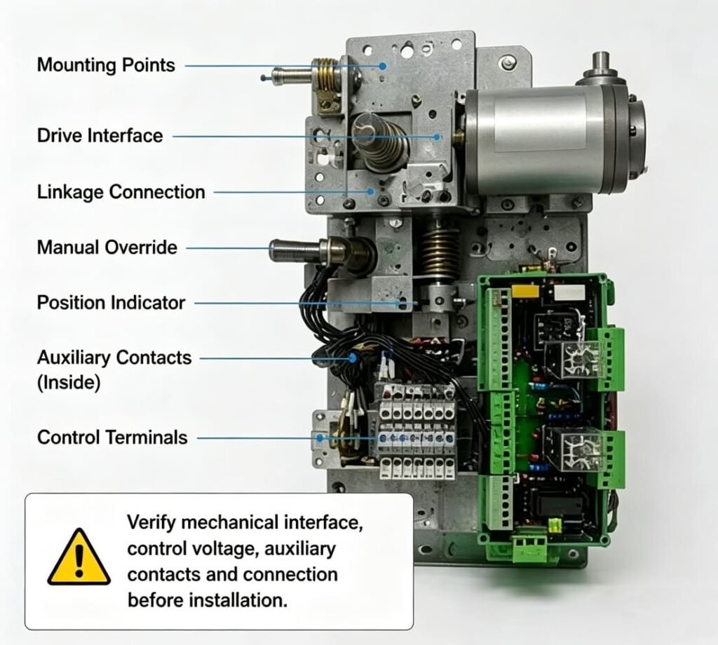
Before ordering a SafeRing motor retrofit, confirm:
- RMU / module configuration
- Existing operating mechanism type
- Mechanical mounting points
- Drive interface
- Control voltage & AC/DC arrangement
- Auxiliary contacts and limit‑switch layout
- Interlocking arrangement
- Available installation space
Identical nominal voltage does not guarantee mechanical interchangeability.
How to Select a Compatible Replacement Mechanism
Submitting only “ABB SafeRing motor mechanism” to suppliers delivers insufficient information. Provide the following data:
| Information | Purpose |
|---|---|
| Switchgear model | Identifies equipment platform |
| Module type | Determines applicable mechanism |
| Rated voltage | Validates configuration |
| Existing mechanism | Mechanical compatibility reference |
| Control voltage | Avoid electrical mismatch |
| AC/DC supply | Confirm control arrangement |
| Auxiliary contacts | Match feedback requirements |
| Nameplate photo | Equipment identification |
| Mechanism photo | Document mounting & linkage |
| Electrical schematic | Validate control logic |
Capture 3‑4 clear photos: full switchgear nameplate, existing motorized unit, mounting‑drive interface and control terminal area. Include part numbers if legible.
Motorized RMU Mechanism and Remote Operation
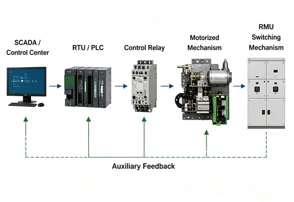
When integrated into distribution automation, signal flow follows this chain: SCADA / Control Centre → RTU / PLC → Control Relay → Control Wiring → Motorized Operating Mechanism → RMU Switching Mechanism → Auxiliary Feedback → RTU / SCADA
Any link failure can mimic a motor fault. For instance, functional motor action paired with wrong SCADA position feedback points toward auxiliary‑contact circuits. Always test SafeRing remote operation as a full system.
Common Mistakes During Mechanism Replacement
- Selecting purely by voltage: Same‑voltage units may have incompatible mechanical interfaces.
- Blind motor replacement before troubleshooting: Relay, fuse or interlock faults will persist with new hardware.
- Ignoring auxiliary feedback: Mechanical operation does not equal correct remote status indication.
- Copying legacy wiring without schematic validation: High risk for retrofit‑project mis‑wiring.
- Bypassing safety interlocks: Creates dangerous operating hazards.
FAQ: SafeRing Motorized Operating Mechanism
Q: What control voltage does a SafeRing motor use? A: Options cover 24 V, 48 V, 60 V, 110 V, 220 V. Confirm via nameplate, equipment documentation and schematics.
Q: Why is my SafeRing motor not working? A: Inspect control supply, fuses, wiring, relays, auxiliary switches, limit switches and interlocks first. Then check motor and mechanical transmission.
Q: Can I replace a SafeRing motorized operating mechanism? A: Compatible aftermarket replacement is feasible only after matching switchgear configuration, mechanical interface, control voltage and auxiliary functions.
Q: Can an existing SafeRing be upgraded for motor operation? A: Qualified configurations support motor‑coil retrofit. Verify compatibility against existing hardware before modification.
Q: Is an RMU motorized operating mechanism universal? A: No. “RMU motorized operating mechanism” is a generic term; interfaces vary by manufacturer and switchgear family.
Q: What information is needed to identify a replacement? A: Switchgear nameplate, module type, mechanism photos, control voltage, schematics and visible part numbers.
Submit your switchgear technical details for a compatible replacement quotation.
Technical Review: This is an engineering‑focused maintenance and procurement guide. Cross‑validate against official documentation and site conditions before field work. Safety note: Medium‑voltage switchgear maintenance, testing and replacement shall only be performed by qualified personnel complying with site safety procedures and local electrical regulations.
Need help identifying your SafeRing motorized operating mechanism replacement?
Share your switchgear nameplate, mechanism photos and technical parameters. Our medium‑voltage engineering team will review compatibility and provide a tailored quotation.