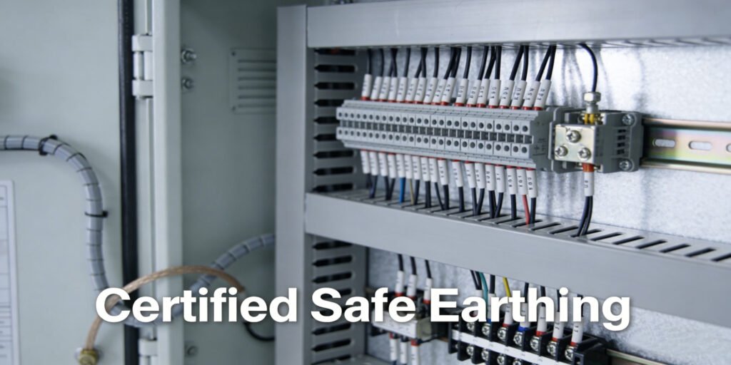
Proper earthing in switchboard is one of the most critical steps in electrical installation. It protects equipment, prevents electric shock, ensures system stability, and meets international safety standards. Without correct earthing, switchboards risk overvoltage, short circuits, fire hazards, and serious injury to operators.
In this guide, we explain how to do earthing in switchboard professionally — covering purpose, types, materials, step-by-step installation, and best practices. This guide applies to industrial, commercial, and residential switchboards, following IEC and NEC safety principles.
Why Is Switchboard Earthing Essential?
Earthing (or grounding) connects non-current-carrying metal parts of the switchboard to the earth. Its main roles include:
- Diverting fault current safely to the ground
- Protecting people from electric shock
- Stabilizing voltage during surges
- Preventing damage to breakers, cables, and connected devices
- Ensuring protective devices (MCB, MCCB, RCD) trip correctly
Any switchboard — whether main distribution board, sub-switchboard, or control panel — must have reliable earthing to operate safely.
Types of Earthing Used in Switchboards
Two main systems are widely used for switchboard earthing:
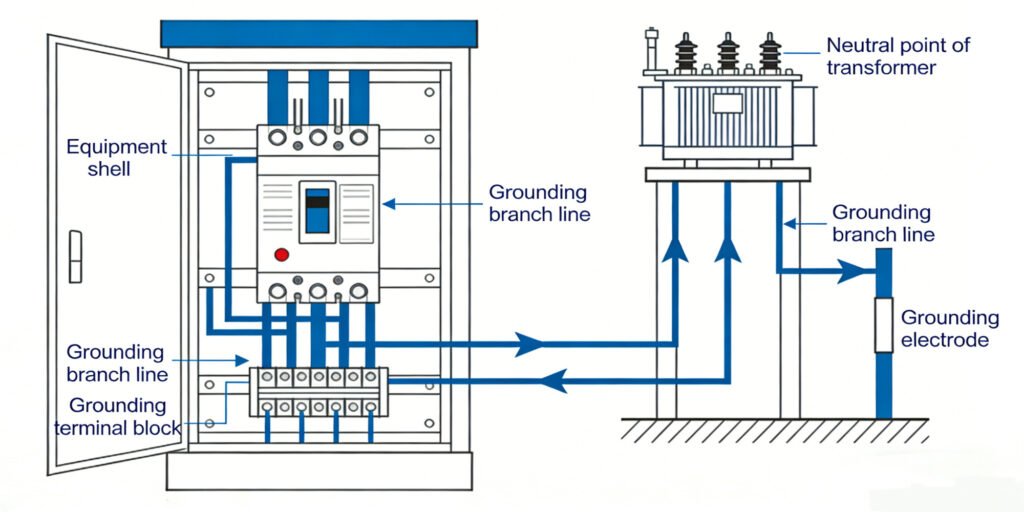
1. Equipment Earthing (Protective Earthing)
Connects the metal body, frame, enclosure, and door of the switchboard to the earth electrode. This is the most important type for safety.
2. System Earthing (Neutral Earthing)
Connects the neutral point of the power supply to the earth. It stabilizes the system and balances voltage.
Both must be installed separately but work together for full protection.
Tools & Materials Required
Before starting, prepare these standard items:
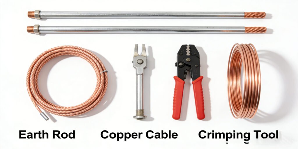
- Earth electrode (copper rod or plate)
- Copper earth strip or earth cable
- Lugs and crimping tools
- Nut, bolt, and washer
- Earth pit with charcoal and salt
- Torque wrench
- Multimeter or earth tester
Using high-quality copper components ensures low earth resistance and long-term performance.
Step-by-Step: How to Do Earthing in Switchboard
Follow this professional procedure to ensure safe and compliant installation.
1. Prepare the Earth Electrode
Drive a copper earth rod into the earth pit. For better conductivity, fill the pit with a mixture of charcoal and salt. This maintains low resistance even in dry weather.
2. Lay the Earth Cable
Run a dedicated copper earth cable from the earth electrode to the switchboard. Avoid sharp bends and ensure the cable is protected from mechanical damage.
3. Install the Earth Busbar
Inside the switchboard, install a main earth busbar — usually made of tinned copper. All earth connections will link to this bar.
4. Connect Metal Parts to Earth Busbar
Connect:
- Switchboard frame
- Inner metal structures
- Mounting plates for breakers
- Metal door
- Instrument earth terminals
Each connection must be tight, clean, and free of paint or rust.
5. Connect Neutral Earth (If Required)
For systems that require neutral earthing, link the neutral busbar to the earth bar using a proper link or connector. Follow local wiring codes.
6. Tighten All Connections
Use a torque wrench to ensure proper tightening. Loose connections increase resistance and create heat or spark hazards.
7. Test Earth Resistance
Use an earth tester to measure resistance. For most industrial and commercial switchboards, the value should be below 1–5 ohms depending on regulations. Low resistance = effective earthing.
8. Label and Inspect
Mark the earth bar clearly. Perform a visual inspection to confirm no loose wires, no crossed connections, and proper insulation on live parts.
Common Mistakes to Avoid
- Multiple devices sharing one small earth wire
- Loose or corroded connections
- Painting over earth contact points
- Using aluminum instead of copper for earthing
- Insufficient earth pit treatment
- Skipping earth resistance testing
These mistakes can make earthing ineffective and dangerous.
Benefits of Proper Earthing in Switchboard
- Maximum protection against electric shock
- Longer lifespan of switchgear and components
- Reliable operation of protection devices
- Compliance with IEC, NEC, and local safety standards
- Reduced risk of fire and electrical failures
Conclusion
Earthing in switch board is not just a technical step — it is a safety requirement. Knowing how to do earthing in switchboard properly ensures your electrical system is safe, stable, and durable. Always use quality materials, follow correct procedures, and test earth resistance to maintain a safe installation.
For high-quality switchboards, earthing components, and professional electrical solutions, explore our full range of reliable products designed for safety and performance.
Earthing Switch: Protection for Switchgear & Power Systems
What is the earthing switch in switchgear?-XiZiEnergy
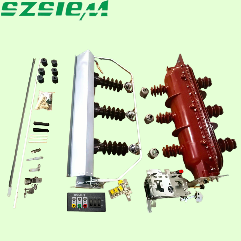
Professional Medium & High Voltage Electrical Equipment Manufacturer